4
CONTENTS
1. Introduction
(1) Introduction
················································································· 6
(2)
Specification
················································································ 7
(3) Part Name
···················································································· 8
2. Layout Drawing ·············································································· 9
3. Installation and Moving
(1) Installation of the machine
·························································· 10
(2) Transportation
············································································ 11
(3) Cleaning before operation
···························································· 12
(4) Coolant
······················································································ 12
(5) Power Source Facility
·································································· 13
4. The description of Control box ······················································ 14
5. Operation
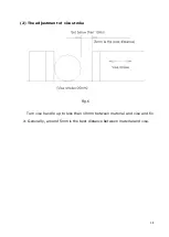
(1) The adjustment of cutting stroke
·················································· 17
(2) The adjustment of vise stroke
······················································ 18
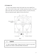
(3) Angular Cut
················································································ 19
(4) Fixed Vise Jaw
············································································ 20
(5) Stopper block
············································································· 20
(6) Saw Blade
··················································································· 21
(7) Vise Pressure Adjustment
···························································· 22
(8) Timer Adjustment
······································································· 23
(9) Saw Head Speed Control
······························································ 24
Summary of Contents for DCS - Series
Page 9: ...9 2 Layout Drawing Fig 2 ...
Page 26: ...26 7 Hydraulic System 1 Hydraulic Circuit Fig 13 ...
Page 28: ...28 8 Electric System 1 Electric Circuit ...
Page 29: ...29 Fig 14 ...
Page 33: ...33 4 Assembly DWG Stand Assembly Fig 15 ...
Page 35: ...35 Table Assembly Fig 16 ...
Page 37: ...37 Column Assembly Fig 17 ...
Page 39: ...39 Coolant Blade cover Assembly Fig 18 ...
Page 43: ...43 Gear Box Assembly Fig 20 ...


