background image

7

Donaldson Company, Inc.

Standard Equipment

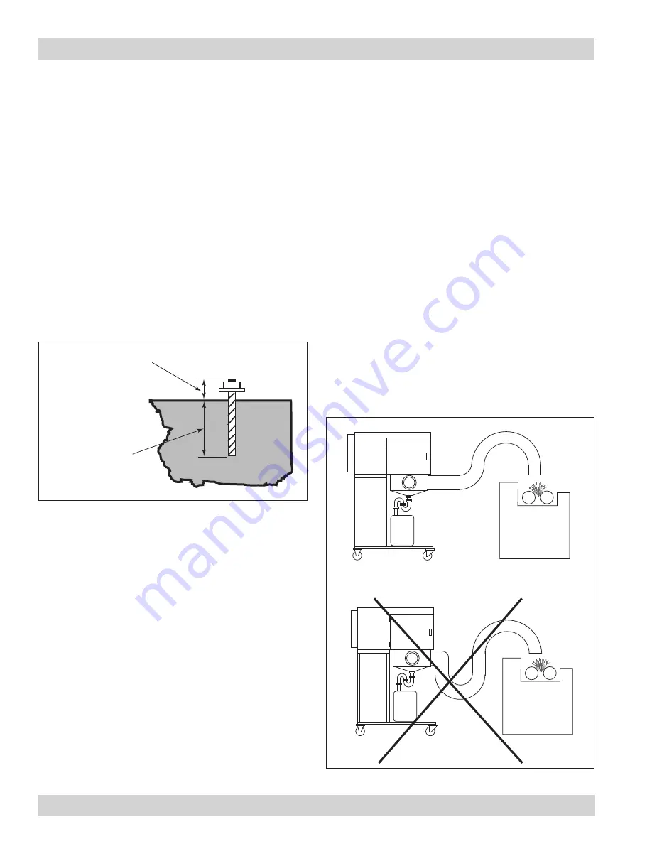
Anchor should project

a minimum of 1 3/4-in

and account for nut, 

washer, base plate 

and shims/grout.

Embedment depth

Typical Foundation Anchor

Provisional Anchor Bolt Recommendations

1.  Consider Hilti HIT-HY 200 Anchor System or 

equivalent. Quantity of anchor bolts should match the 

number of holes provided in the base plates.

2.  Anchor diameter is typically 1/8-in less than 

baseplate hole diameter.

3.  Corrosive environment or outdoor installation may 

require stainless steel anchors.

General Installation

1.  Apply a generous amount of sealant when installing 

attachments.

2.  Position the collector above the mist-capture zone. 

See Collector Positioning.

3.  Do not allow a P-Trap to form when using flexible 

duct. See Flex-Duct Positioning.

4.  On enclosed-machine installations, mount the unit 

as far from the chip conveyor opening as possible. 

Installing too close allows the  negative pressure 

created by the unit to draw clean shop air, not 

mist, into the collector. See Enclosed-Machine 

Installation.

5.  On open-machine installations, position the unit’s 

pick-up hood a minimum of 305 mm (12-inches) from 

the mist source. Avoid mounting the pick-up hood too 

close to the mist source of an open machine such 

as a wet surface grinder. Installing too close can 

shorten filter life as the unit will collect large droplets 

and particulate instead of mist. See Open Machine 

Installation.

A variety of configuration and mounting options are 

available with the WSO M.  The WSO M can be mounted 

directly on the roof of a machining center, suspended 

overhead, or stand-mounted.

machine

center

Correct

machine

center

Incorrect

P-trap

Flex Duct Positioning

Summary of Contents for WSO M

Page 1: ...l is property of the owner Leave with the unit when set up and start up are complete Donaldson Company reserves the right to change design and specifications without prior notice Illustrations are for reference only as actual product may vary WSO M Mist Collector Machine Mountable Installation and Operation Manual Installation Operation and Service Information IOM AK0300401 Revision 2 ...

Page 2: ...ibility or liability for the suitability of any fire and or explosion mitigation strategy or any items incorporated into a collector as part of an owner operators hazard mitigation strategy Improper operation of a dust control system may contribute to conditions in the work area or facility that could result in severe personal injury and product or property damage Check that all collection equipme...

Page 3: ...nit Location 5 Site Selection 5 Foundations or Support Framing 5 Rigging Instructions 5 Hoisting Information 5 Electrical Wiring 6 Standard Equipment 7 Provisional Anchor Bolt Recommendations 7 Standard Equipment Options 9 Flush Mount with Inlet Gasket 9 Flanged Inlet Hopper with Legs 9 Ceiling Mount Installation 10 Collector Stand 11 Inlet Hopper with Flex Duct 12 Inlet Hopper with Vibration Isol...

Page 4: ...ter media specifically designed for mist collection is a standard offering on the product line The primary filter is uniquely designed for either water based coolants straight oils or thermally generated smoky applications Standard options include drain collection containers adjustable floor mounting stands and afterfilters The WSO M machine mountable unit is powered by a blower and motor mounted ...

Page 5: ...r gauge 10 Control power 200 Volt 50 60 Hz 220 Volt 50 60 Hz 380 Volt 50 60 Hz If unit was supplied with a Record Drawing the specifications on the drawing will supersede the standard specifications above WSO Mist Collector WSO M 2 Rating and Specification Information ...

Page 6: ... The air passes through a reusable first stage filter designed to collect and coalesce large droplets and particles The primary stage of filtration is the pleated filter cartridge specifically designed to collect coalesce and drain fine mist As the mist coalesces the droplets are big enough to run down the cartridge and drain back into the collector The droplets will drain on both the inside and o...

Page 7: ...e agent must complete installation and service of this equipment All shipping materials including shipping covers must be removed from the unit prior to or during unit installation Failure to remove shipping materials from the unit will compromise unit performance Inspect unit to ensure all hardware is properly installed and tight prior to operating collector Installation Use proper equipment and ...

Page 8: ...align holes in section flanges during assembly Unit Location Donaldson Torit equipment is not designed to support site installed ducts interconnecting piping or electrical services All ducts piping or electrical services supplied by others must be adequately supported to prevent severe personal injury and or property damage When hazardous conditions or materials are present consult with local auth...

Page 9: ...stallation service or maintenance work must be performed by a qualified electrician and comply with all applicable national and local codes Turn power off and lock out electrical power sources before performing service or maintenance work Do not install in classified hazardous atmospheres without an enclosure rated for the application All electrical wiring and connections including electrical grou...

Page 10: ...g flexible duct See Flex Duct Positioning 4 On enclosed machine installations mount the unit as far from the chip conveyor opening as possible Installing too close allows the negative pressure created by the unit to draw clean shop air not mist into the collector See Enclosed Machine Installation 5 On open machine installations position the unit s pick up hood a minimum of 305 mm 12 inches from th...

Page 11: ... WSO M 8 Collector Positioning machine center machine center Correct Incorrect Correct Location Incorrect Location Enclosed Machine Installation Open Machine Installation large droplets and particulate enter pick up hood ...

Page 12: ... Start bolts from the inside of the machine center Do not overtighten Compress gasket 5 mm 3 16 in maximum 7 Install a bolt into every rivnut hole Flanged Inlet Hopper with Legs This flanged inlet hopper option is for installing a collector on a machine center that has a limited amount of unobstructed top surface 1 Open the units access door and remove the primary and first stage filters 2 Remove ...

Page 13: ...verhang Ensure weight of oil laden unit plus weight of required materials and equipment will be adequately supported Failure to comply may result in personal injury and or property damage 1 Verify that the ceiling attachment points can bear the live load 2 Use properly sized cable or chain to attach to each of the four eyebolts to suspend the unit from the ceiling 3 To prevent sway position the ch...

Page 14: ...mm 66 to 102 in 1 Install customer supplied 3 8 16 anchor bolts in the floor extending 38 mm 1 1 2 in above surface 2 Level the collector stand and tighten anchor bolts securely 3 Lift the unit and remove the bolts from the access panel located on the bottom of the unit Remove bolts only Do not remove access panel 4 Adjust the stand height by loosening the four locking bolts on the upper portion o...

Page 15: ...tern on the bottom of the unit and secure using 6mm bolts and washers supplied Note Install a 6mm bolt into every rivnut 6 Fasten one end of the flexible duct to the collar using a six inch hose clamp 7 Position the inlet collar on the machine center and trace the inlet opening and bolt pattern Remove inlet collar cut inlet hole and drill bolt holes using a 3 16 in diameter drill bit 8 Apply a 6mm...

Page 16: ...the bottom of the unit and secure using 6mm bolts and washers supplied 7 Attach remaining leg to the right side of the unit following the same procedure 8 Turn unit upright lift into position over the machine center and lower slowly Do not remove crane 9 Match drill four holes in the machine center for securing the legs 10 Position the inlet collar on the machine center and trace the inlet opening...

Page 17: ...the outside of the bolt pattern 5 Align the top flange of the hopper with the bolt pattern on the bottom of the unit and secure using 6mm bolts and washers supplied Note Install a 6mm bolt into every rivnut 6 Fasten the flexible duct to the 152 mm 6 in side inlet on the impact separator using a hose clamp 7 Connect opposite end of flexible duct to a customer supplied angular nozzle inlet collar or...

Page 18: ...and hardware latch HEPA or 95 DOP final filter airflow HEPA or 95 DOP Final Filter Replacement Electrical Connection Electrical installation service or maintenance work must be performed by a qualified electrician and comply with all applicable national and local codes Turn power off and lock out electrical power sources before performing service or maintenance work Do not install in classified ha...

Page 19: ...d check for proper rotation by removing the inspection cover on the top of the WSO M and viewing the wheel rotation To reverse rotation single phase power supply Follow manufacturer s instructions on the motor s nameplate To reverse rotation three phase power supply Turn electrical power OFF at source and switch any two leads on the motor junction box Do not interchange a power lead with the groun...

Page 20: ... with all applicable national and local codes Turn power off and lock out electrical power sources before performing service or maintenance work Check that the collector is clear and free of all debris before starting Do not install in classified hazardous atmospheres without an enclosure rated for the application 1 Check all electrical connections for tightness and contact 2 Check for proper rota...

Page 21: ...necessary 6 For a typical installation Donaldson recommends filter installation when the gauge indicator needle is half way into the red zone See First Stage Filter Cleaning and Installation Do not attempt to clean or wash the primary filter Replace only Do not operate the unit without the first stage or primary filter in place Significant reduction in final filer life can result Filter Removal an...

Page 22: ...and out of the unit while the bag is pulled up over the bottom of the cartridge 2 Place new filter on the filter retention platform gasket side up Slide filter back as far as it will go Note The primary filter must be replaced Do not wash 3 Lift the filter retention lever up and close access door latch HEPA or 95 DOP final filter airflow primary filter cartridge filter retention lever Final Filter...

Page 23: ... access doors Electrical circuit overload Check that the power supply circuit has sufficient power to run all equipment Clean air outlet discharging oil mist Filters not installed correctly See Filter Removal and Installation Filter damage dents in the end caps gasket damage or holes in media Replace filters as necessary Use only genuine Donaldson replacement parts See Filter Removal and Installat...

Page 24: ...ufficient hopper discharge Plugged hopper screen Remove and clean hopper screen Liquid leaking from collector door Access door not closed tight Check that access door is in place and secured Missing gasket on access door Install new door gasket Troubleshooting ...

Page 25: ...WSO Mist Collector WSO M 22 Service Notes Date Service Performed Notes ...

Page 26: ...23 Donaldson Company Inc Service Notes Date Service Performed Notes ...

Page 27: ......

Page 28: ...NTIES OR GUARANTEES EXCEPT AS STATED IN THIS PARAGRAPH AND ALL OTHER WARRANTIES INCLUDING MERCHANTABILITY AND FITNESS FOR A PARTICULAR PURPOSE WHETHER EXPRESS OR IMPLIED ARE HEREBY EXPRESSLY EXCLUDED AND DISCLAIMED Donaldson Company Inc is the leading designer and manufacturer of dust mist and fume collection equipment used to control industrial air pollutants Our equipment is designed to help red...

Reviews: