Downflo Oval, DFO 1-1 to 3-3
12
103
N N L
104
105
TR1
FU1
ground lug
120-Volt AC
to solenoid
enclosure
120-Volt AC
PS1
SEQ1
FU1
ground
lug
120-Volt AC
to solenoid enclosure
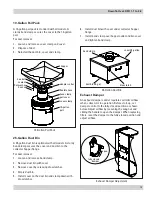
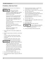
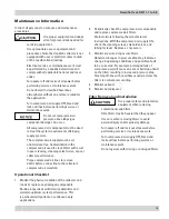
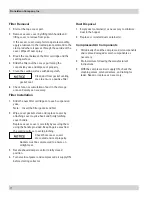
Downtime Cleaning
Delta P Control
Remote-Mount Cleaning Controls
Remote-Mount Cleaning
Remote-mount control panels are not equipped with
a motor starter and require 120-Volt AC, single-phase
power to be wired directly to the control panel. Separate
power must be supplied directly to the motor. See the
wiring diagram on the motor's nameplate and Motor
Wiring Instructions.
Downtime Cleaning
Wire 120-Volt AC directly to the control panel PLC
terminal block at Terminals L, N, and G.
Solenoid Connection
Connect solenoid valves to the PLC relay outputs located
inside the control panel.
Delta P Cleaning
Wire 120-Volt AC power directly to the control panel two-
point terminal block located on the 3-pin timer subpanel.
Solenoid Connection
Wire each solenoid valve to the 3-pin timer board.
Motor Wiring Instructions
For Customer-Supplied Motor Starters
1. Power is always routed through one or both of the
top electrical openings and through an internal
bulkhead knockout provided on the blower motor
plate inside the collector.
2. Remove electrical-access panels and set aside.
3. Using the wiring diagram on the motor, wire directly
to motor. Do not wire through the control panel.
Use appropriate wire gauge for rated amp load as
specified by local codes.
4. With power supply ON, check the operation of
the motor and fan rotation. The fan can be viewed
through the control panel access door. Proper
rotation is counterclockwise from the top of the
collector.


