background image

2

SECTION A. INSTALLATION

2. VENTILATION

The installation shall be made in such a manner as to
separate the combustion system from the living space of the
mobile home or recreational vehicle. Openings for air supply
or for venting of combustion products shall have a minimum
dimension of not less than 1/4 inch.

Proper installation requires one fresh air intake and one
upper exhaust vent. The ventilation kits shown in this
instruction manual have been certified for use with the
refrigerator model listed in the Table. For "Certified Vent
System Kits" see Section B. The ventilation kits must be
installed and used without modification. An opening toward
the outside at floor level in the refrigerator compartment must
be provided for ventilation of heavier-than-air fuel gases. The
lower vent of the recommended kits is provided with proper
size openings. The flow of combustion and ventilation air
must not be obstructed.

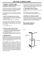
NOTEThe upper vent should be
centered over the condenser coil
at the back of the refrigerator.

FIG. 1

1. GENERAL INSTRUCTIONS

This appliance is designed for storage of foods and
storage of frozen foods and making ice.

The refrigerators outlined herein have been design certified
by A.G.A. under  ANSI Z21.19 Refrigerator Standard for
installation in a mobile home or recreational vehicle and are
approved by the Canadian Gas Association.

The certifications are, however, contingent on the installa-
tion being made in accordance with the following instructions
as applicable.

In the U.S.A., the installation must conform with:
1. National Fuel Gas Code ANSI Z223.1-(latest edition)
2. Manufactured Home Construction and Safety Standard,
Title 24 CFR, Part 3280
3. Recreational Vehicles ANSI A119.2-(latest edition).

The unit must be electrically grounded in accordance with
the National Electric Code ANSI/NFPA 70-(latest edition)
when installed if an external alternating current electrical
source is utilized.

4. Any applicable local code.

In Canada, the installation must conform with:
1. Current CGA B 149 Gas Installation Codes
2. Current CSA Standard Z 240.4 GAS-EQUIPPED REC-

REATIONAL VEHICLES AND MOBILE HOUSING

3. Any applicable local code
The unit must be electrically grounded in accordance with
the CANADIAN ELECTRICAL CODE C 22 Parts 1 and 2.

The lower side vent is fitted with a panel which provides an
adequate access opening for ready serviceability of the
burner and control manifold of the refrigerator. This should be
centered on the back of the refrigerator.

3. CERTIFIED INSTALLATION

Certified installations require one roof vent and one lower
side vent.

For certified vent system kits, see Section B.
For further information, contact your dealer or distributor.

4. METHOD OF INSTALLATION

The method of installation is shown in FIG. 1. It is essential
that all maximum or minimum dimensions are strictly main-
tained as the performance of the refrigerator is dependent on
adequate flow of air over the rear of the refrigerator.

Summary of Contents for RM2607

Page 1: ...OR YOUR SAFETY Do not store or use gasoline or other flammable vapors and liquids in the vicinity of this or any other appliance WARNING Improper installation adjustment alteration service or maintena...

Page 2: ...e however contingent on the installa tionbeingmadeinaccordancewiththefollowinginstructions as applicable In the U S A the installation must conform with 1 National Fuel Gas Code ANSI Z223 1 latest edi...

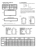
Page 3: ...ator and the wall behind the refrigerator NOTE Clearance N isthedistancebetweenthebottom of the lower vent to the roof material For ventilation height refertoSectionA Installation Item5 Ventilation He...

Page 4: ...equence in securing refrigerator in enclosure can cause leakage between the frame and cabi net The plastic caps are snapped in the front base to cover the screw heads and the decoration strip is secur...

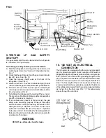
Page 5: ...oceeding Be careful not to damage burner jet Replace cover and turn the main switch OFF and back ON See Section C Operation Instructions Item2 ControlPanel Normaloperationof the burner should return A...

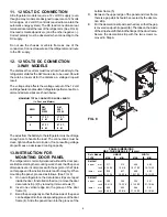
Page 6: ...nded wire sizes are shown below MAXIMUM TOTAL CONDUCTOR WIRE LENGTH In Feet and Meters RM RM AWG 2607 2807 215W 215W 10 17 FT 17 FT 5 M 5 M 8 27 FT 27 FT 8 M 8 M Thewiresfromthebatterytotherefrigerato...

Page 7: ...Plastic caps for the empty holes are in the parts bag Remountthedoorsandthehingepinsinthereverseorderof theirremoval Unscrewthehandlesandrefastenthemonthe opposite side of the door Insert the plastic...

Page 8: ...be leveled only so it is comfortable to live in no noticeable sloping of floors or walls When the vehicle is moving the leveling is not critical as the rolling and pitching motion of the vehicle will...

Page 9: ...o the OFF then ON position If the control is switched to AC operation while the CHECK indicator lamp is on it will function properly but the CHECK indicator lamp will not go off until the main power O...

Page 10: ...n ON position If the control is switched to AC or DC operation while the CHECK indicator lamp is on it will function properly but the CHECK indicator lamp will not go off until the main power ON OFF b...

Page 11: ...d in direct contact with the freezer shelf Toreleasetheicecubes seizethetraywithbothhandsand twist the tray Cubes not required should be replaced in the tray Refill the tray with water and replace the...

Page 12: ...per vent and area between these openings for any obstructions such as bird insect nests spider webs etc Clean the coils on the back of the refrigerator Use a soft bristled brush to dust off the coils...

Page 13: ...lue cap 8 Clean burner tube with a brush Blow out burner with compressedair 9 Beforeremovingburnerjet cleanburnerareaofsoot andscalethatfelloutoffluetube Removetheburner jet Soak the jet in wood alcoh...

Page 14: ...rized service center for parts and repairs as needed F FUSES The2 wayAMESmodelsareequippedwith2fuses onefor the refrigerator control system and one for the AC cartridge heater The 3 way AMES models ar...

Reviews: