16
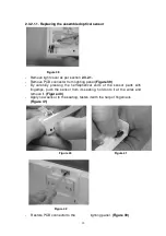
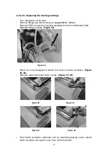
- When ready with the operation, clip back the lighting panel in its place, and
order the cables.
- Place light cover in grooves located in internal container, clip on, and
tighten light cover screws.
(Figure 42)
After disassembling this electrical part, no electrical insulation resistance test
is necessary.
After assembling, connect the appliance to the electrical supply, and check
operation through the self-test of the electronics.
(see 2. 3. 1. 2.)
2.3.2.2. Checking and replacing parts connected to the Fuzzy controller
These parts can be made available as follows:
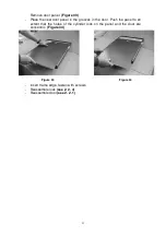
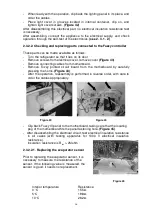
- Turn the refrigerator so that it lies on its door
- Remove screws from electrical cover, remove cover
(Figure 43)
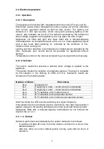
- Remove connecting cables from motherboard.
- Remove Fuzzy printed circuit board from the motherboard by carefully
pressing the horns.
(Figure 44)
- After the operation, reassembly is performed in reverse order, with care to
order the cables appropriately.
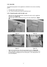
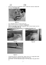
- Clip back Fuzzy III panel to the motherboard, taking care that the locating
peg of the motherboard fits the panel fastening hole.
(Figure 45)
- After disassembling the electrical circuit, test electrical insulation resistance
in all cases (with testing apparatus for 1000 V electrical insulation
resistance).
Insulation resistance is R
ins
> 2Mohm
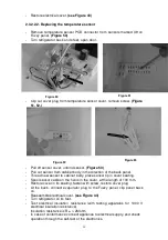
2.3.2.2.1. Replacing the evaporator sensor
Prior to replacing the evaporator sensor, it is
necessary to measure the resistance of the
sensor. If the following value is measured, the
sensor is good, it needs no replacement.
Interior temperature
Resistance
0 °C
15.5
Ω
5°C
19.8
Ω
10°C
26.2
Ω
Figure 45
Figure 43
Figure 44

