background image

(36)

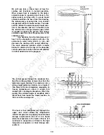
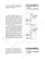
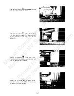
and onto the orifice and burner assembly.

Remember that except 

for the connection 

piece,

all fittings are O-ring sealed. 

Whenever the

system is separated the O-rings must be

replaced.

ORIFICE & BURNER

ASSEMBLY

(37)

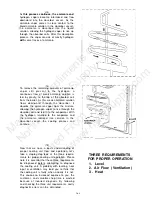
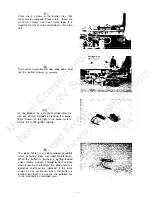
To diagnose the gas system, connect a

manometer to the test point. With the

thermostat on maximum you must have 11

inches water column pressure at this point. 

If

you have 11 inches pressure, your problem

Is to the right of the test point. If you do not

have 11 inches water column pressure, the

problem Is to the left.

(38)

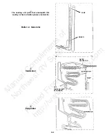
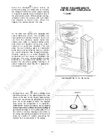
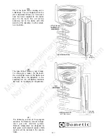
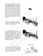
Let’s take a closer look at the gas thermostat.

In this drawing we will review how a thermostat

functions. When the thermostat is working

properly, the manometer will read line pressure

when set at maximum and the refrigerator is

trying to cool. From this drawing you can see

the gas flow when the refrigerator is trying to

cool. The gas flows through the thermostat at

line pressure without restriction. The valve is

(39)

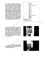
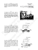
The valve is now closed and the gas must flow
through the by-pass screw; the gas is now

diverted through the by-pass screw, which

regulates the size of the low flame. This

condition can only exist when the refrigerator is

cold or the thermostat is set to minimum or off.

If the sensing tube has lost its pressure, even

with the thermostat set on maximum, you will

have only low flame.

 DIAL SHAFT

open at this time.

VALVE

 DIAL SHAFT


SCREW CLOSED VALVE

D-6-13

Manual 

Compliments 

of 

Northwest 

RV 

Supply 


Printed 

From 

 http://www.nwrvsupply.com

Summary of Contents for MANUAL REFRIGERATOR

Page 1: ...Parkway Elkhart IN 46515 219 295 5228 205 E Fenn St LaGrange IN 46761 219 463 2191 Technical Services Department 509 S Poplar St LaGrange IN 46761 219 463 4858 OS1286 8 89 D l Diagnostic Service Manu...

Page 2: ...NOTES D 2 M a n u a l C o m p l i m e n t s o f N o r t h w e s t R V S u p p l y P r i n t e d F r o m h t t p w w w n w r v s u p p l y c o m...

Page 3: ...s Operation Piezo Igniter No Gas Operation Automatic Reigniter Operation and Diagnosis Dometic Manual Refrigerators Glossary of Terms Service Bulletins D 4 l D 4 2 D 4 3 D 4 4 D 6 1 D 8 l D 9 l D 3 M...

Page 4: ...Necessary NOT OK Replace if Defective OK c Check wiring Correct as Necessary NOT OK OK D Check Switch NOT OK Correct as Necessary Page D 6 20 Para 66 OK E V Check Thermostat Correct as Necessary NOT O...

Page 5: ...ctor Switch NOT OK Correct as Necessary Page D 6 20 Para 66 OK c V Check Thermostat Correct as Necessary Continuity Check NOT OK OK D Check 120 Volt Heater NOT OK Correct as Necessary Ohm s Reading Bu...

Page 6: ...orrect as Necessary Page D 6 13 Para 37 Check Flue Burner NOT OK Correct as Necessary No Obstructions OK F Check Piezo Resistance I NOT OK Correct as Necessary Page D 6 l 8 Para 58 OK G V Check Piezo...

Page 7: ...2 Volt D C Supply Correct as Necessary NOT OK I OK Check Switch NOT OK Correct as Necessary Page D 6 20 Para 66 I OK _E Check Thermostat NOT OK Correct as Necessary Check for Continuity OK F V Clean A...

Page 8: ...NOTES D 5 M a n u a l C o m p l i m e n t s o f N o r t h w e s t R V S u p p l y P r i n t e d F r o m h t t p w w w n w r v s u p p l y c o m...

Page 9: ...OPERATION DIAGNOSIS OF DOMETIC MANUAL REFRIGERATORS D 6 1 M a n u a l C o m p l i m e n t s o f N o r t h w e s t R V S u p p l y P r i n t e d F r o m h t t p w w w n w r v s u p p l y c o m...

Page 10: ...it operates THE ABSORPTION SYSTEM 3 The sealed combustion unit contains a mixture of ammonia water and a rust inhibiting agent After this solution is introduced into the coils this unit is pressurize...

Page 11: ...on process include the Boiler or Generator 5 Condenser 6 Evaporator PUMP BOILER l WATER SEPARATOR I GAS TEMPERATUR EXCHANGER I I 1 D 6 3 M a n u a l C o m p l i m e n t s o f N o r t h w e s t R V S u...

Page 12: ...reation al vehicle applications TEMPERATURE EXCHANGER TEMPERATURE EXCHANGER _ 9 Before this cooling system can properly extract heat from the cabinet of the refrigerator three requirements for prop er...

Page 13: ...p of the absorber coils to perform a function that we will discuss in further detail later in the program 11 The air that passes through the condenser fins from the venting system removes heat from th...

Page 14: ...the evaporator With the hydrogen returned to the evaporator and the ammonia remixed into solution in the absorber vessel the cooling process can continue 15 Now that we have a basic understanding of p...

Page 15: ...efrigerator will not loosen or dislodge the blockage The only recommended service procedure is to replace the cooling unit To prevent this occurrence proper leveling is of utmost importance when the R...

Page 16: ...cooling coils are not normally damaged in this fashion and once proper leveling is main tained the cooling process will resume 20 Spirit or bubble levels are no longer being supplied with the new styl...

Page 17: ...joints in the enclosure be sealed The under counter installation is different The addition of a metal chute the width of the enclosure that extends from the upper side vent will help eliminate the po...

Page 18: ...is the only part we cannot field check with test equipment yet it is the simplest and quickest part to diagnose CONDENSER EVAPORATOF TEMPERATURE EXCHANGER BOILER DIAGNOSING THE COOLING UNIT 27 After...

Page 19: ...this unit will be warm at the boiler and extremely hot at the absorber In this condition we are still boiling ammonia but have no hydrogen for evaporation 30 The following section of the program exam...

Page 20: ...on gas and electric thermostat 3 4 through the safety valve thermocouple 35 test housing UNDERSTANDING THE GAS SYSTEM SHUT OFF VALVE I GAS LINE CONNECTION PIECE COMBINATION GAS ELECTRIC T H E R M O S...

Page 21: ...properly the manometer will read line pressure when set at maximum and the refrigerator is trying to cool From this drawing you can see the gas flow when the refrigerator is trying to cool The gas flo...

Page 22: ...eing adjusted If the manometer reads 11 inches the problem of no cooling lies in the burner assembly flue pipe or venting 41 If you have less than 11 inches water column pressure the next step would b...

Page 23: ...loy failure safety device valve housing and cap an electro magnet and a thermocouple which generates 14 to 30 millivolts when heat is applied to the tip It is used to energize the electro magnet in th...

Page 24: ...cohol base solvent and allow to air dry DO NOT use a pin or needle This will distort or shatter the orifice 48 If you determine that disassembly is required be aware there are two model designs for ma...

Page 25: ...ne at the refrigerator I 5 3 Remove 3 screws on the burner cover plate The sheet metal assembly should now slide out from the back of the refrigerator Remove the 2 screws from the plastic cover Also t...

Page 26: ...system on the left is the igniter reigniter 58 The piezo lighter is a self contained assembly which generalty does not need maintenance When the button is pushed a spring loaded striker creates a spa...

Page 27: ...12 volts If the igniter is receiving 12 volts and produces no spark it must be checked for operation 61 Turn the refrigerator off and remove the wire between the electrode and igniter Now turn the re...

Page 28: ...uirements for the cooling unit operation or the manual refrigeration please refer to the diagnostic manual For additional technical service assistance contact the Technical Service Department at 219 4...

Page 29: ...NOTES D 7 M a n u a l C o m p l i m e n t s o f N o r t h w e s t R V S u p p l y P r i n t e d F r o m h t t p w w w n w r v s u p p l y c o m...

Page 30: ...cess include hydrogen ammonia water and a rust inhibiting agent 7 CUT OFF VALVE Shut Off Valve Valve where the incoming propane supply is attached This valve is direct coupled to the selector switch b...

Page 31: ...erator vent area SELECTOR SWITCH This is also a circuit interrupter on the 12 volt DC 120 volt AC and gas sides of operation on the refrigerator When the customer selects either DC AC or GAS operation...

Page 32: ...e absorber indicates the fluid circulation within the unit is good BLOCKAGE One of the faults with a cooling unit is blockage This can happen when the unit is operated off level or if too much heat ha...

Page 33: ...t a fault If an adjustment is required repeat the above procedure to determine the effectiveness of the repair SMOOTH FIT PROPER SEAL SMOOTH FIT FIG 1 PROPER SEAL If the door s open when the latch ass...

Page 34: ...re store over the lower hinge pin and reinstall the door s This will raise the door to engage the latch assembly On very rare occasions two 2 washers may be required If the latch assembly still will n...

Page 35: ...all food should be removed for testing Refrigerator Bulletin R55 7A April 1987 6 WOOD BLOCK FIG Al 2 FIG A2 I FC140 Cooling Unit cannot be replaced A Category l RM46 RM46 1 RM663 RM2500 RM360 RM660 R...

Page 36: ...2 RM100 RM763 RM1303 RM760 RM1300 RM2600 RM3600 RM76 1 RM1301 RM2800 RM3800 REMOVAL OF COOLING UNIT 1 2 3 Remove screw holding clamp for capillary tube Pull capillary tube out gently and place aside...

Page 37: ...eater wires from terminal FIG Cl from block a Remove heaters from boiler case FIG Cl D 9 6 3 4 5 6 7 Remove screws holding unit from rear FIG Cl Disconnect green grounding wire FIG Cl Pull out on cool...

Page 38: ...tion Reconnect burner assembly to chimney and replace cover FIG D3 E Category 5 REMOVAL OF COOLING UNIT 1 2 3 4 Remove chimney Remove Remove rear FIG E 1 cover and disconnect burner from FIG El heater...

Page 39: ...pillary tube Pull capillary tube out gently FIG F2 Remove ten 10 screws holding unit from rear FIG Fl 6 Pull out on cooling unit and remove 5 2 5 INSTALL REPLACEMENT COOLING UNIT 1 3 _ 3 Trim the Styr...

Page 40: ...rews holding unit from rear FIG G1 Remove two 2 screws holding gas line gasket FIG Gl 6 l THERMAL MASTIC IS NOT USED G Category 7 RM182 5 6 7 Tighten screws securely to obtain proper seal Install the...

Page 41: ...level but the refrigerator is not due to improper installation Place a level on the bottom of the freezer compart ment and check side to side and front to back levels see FIG Al Use a mirror if necess...

Page 42: ...run the performance test described below with the refrig erator installed then run the same test with the refrigerator removed If there is a definite improvement in performance a venting problem is i...

Page 43: ...very accurate ohmmeter must be used because of the very low readings that will be found For example a 200 watt element will have a reading of 72 ohms less than 1 ohm 5 After two hours of operation ch...

Page 44: ...verheating of the cooling unit and the cooling process will slow down or stop ONE LASTCHECK If the previously mentioned test was performed in air temperatures above and the temperature in the refriger...

Page 45: ...66 RM66E 9283571009 5 2 2002660187 RM66E RM66F 9283599000 51 2002660179 RM66F RM67 928352 1004 5 2 2002660187 l RM67 RM67D 9283521004 5 2 2002660187 l RM67D 9283521004 52 2002660187 l RM75 76 77 76D...

Page 46: ...54045 2 5 48 ___ 0173757022 17 9 RM3800 2934901097 58 2007419217 0173742081 2 7 44 ___ l Models that use brass heating elements in diameter D 9 15 M a n u a l C o m p l i m e n t s o f N o r t h w e s...

Page 47: ...ng elements approximately in diameter NOTE The formula for calculating amps Watts Volts AMPS Volts 120 Amps D 9 16 M a n u a l C o m p l i m e n t s o f N o r t h w e s t R V S u p p l y P r i n t e d...

Page 48: ...ld be drilled in the cooling flange New holes 1 29 mm down 0 Furthermore the hole for the air channel no longer necessary in the burner box should be covered by a piece of aluminium tape No combustibl...

Page 49: ...RM 66 RM 663 RM 763 100 RM 182 RM 235 RM 46 RM 66E RM 76 RM 100 1302 RM RM 36C RM 46E RM 66F RM 77 RM 13C0 1300 RM 211 RM 36E RM 460 RM 660 RM 760 RM 1303 1302 RM RM 360 RM 461 RM 661 RM 761 RA 100 R...

Page 50: ...the cabinet They are also requiring that all literature packaged inside the cabinet from this point on rate electrical input at 120 volt A C Therefore the new spare parts list supplied with the refrig...

Page 51: ...ER SEPARATOR VAPOR PIPE SOLUTION B SOLUTION c LIQUID D VAPOR E HYDROGEN GAS F VAPOR D 9 20 M a n u a l C o m p l i m e n t s o f N o r t h w e s t R V S u p p l y P r i n t e d F r o m h t t p w w w n...

Page 52: ...6 5573 http www nwrvsupply com mail nwrvsupply com Northwest RV Supply carries a large spectrum of surplus used and new RV parts and components Please feel free to visit our website for additional inf...

Reviews: