background image

[page 4]  |  gpelectric.com

WARNING: Before you install and use your Go Power! Smart Converter/Charger, 

be sure to read these safety instruc-

tions. : Before you install and use your Go Power! Smart Converter/Charger.

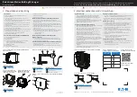
Do not expose the GP Smart Charger to rain, snow, spray, bilge, or dust. To reduce risk of hazard do not 

cover or obstruct the ventilation openings

Adequate space above and below the GPC charger is vital to ensure proper temperature dissipation, and 

avoiding overheating.

To avoid a risk of fire and electronic shock, ensure that existing wiring is in good electrical condition and 

that wire size is not undersized..

Do not operate the GP Smart Charger with damaged or substandard wiring.

Be sure to tighten all connections securely. A loose connection can quickly cause terminals and wires to 

overheat. Review unit labels for recommended terminal torque values.

The battery terminal, not connected to the chassis, has to be connected first. The other connection to be 

made to is from the chassis, remote from the battery and fuel line. The Battery Smart Charger is then to be 

connected to the supply mains.

After charging, disconnect the GP Smart Charger from supply mains. Then remove the chassis connection 

and battery connection, in this order.

Do not attempt to charge non-rechargeable batteries.

Ensure lead acid batteries are placed in a well-ventilated area.

The battery Smart Charger should only be plugged-in to a grounded outlet.

If the power supply cord is damaged, contact Go Power! for instructions.

Never leave the Smart Charger unattended when plugged in.

2. SAFETY INSTRUCTIONS

Summary of Contents for GPC-100-MAX

Page 1: ...X GPC 45 MAX GPC 55 MAX GPC 75 MAX GPC 100 MAX 2021 Go Power Worldwide Technical Support and Product Information gpelectric com Go Power Dometic 201 710 Redbrick Street Victoria BC V8T 5J3 Tel 1 866 2...

Page 2: ......

Page 3: ...CHARGE CONTROLLER OPTIONS 8 5 1 GPC CHARGING 8 5 1 1 REDUCED CHARGE TIMES 8 5 1 2 INCREASED BATTERY CAPACITY 8 5 1 3 REDUCED BATTERY STRESS 8 5 2 EXTERNAL GPC DIMENSIONS 8 6 TROUBLESHOOTING 9 7 WARRA...

Page 4: ...e sure to tighten all connections securely A loose connection can quickly cause terminals and wires to overheat Review unit labels for recommended terminal torque values The battery terminal not conne...

Page 5: ...ess to the battery ensuring long battery life The GPC will also prevent self discharge of the batteries 3 1 THREE STAGE CHARGING OPTION DESCRIPTION This optional system provides an automatic charging...

Page 6: ...turn on and off very slowly minimizing unwanted fan starting noise 3 3 ELECTRICAL SPECIFICATIONS GPC 35 MAX GPC 45 MAX GPC 55 MAX GPC 75 MAX GPC 100 MAX DC Output Voltage No Load approx 13 16 5 VDC O...

Page 7: ...ecting the battery positive to the line side of the breaker and the GPC to the load side Connect Chassis Bonding Lug on the GPC to vehicle chassis or other grounding source 4 2 120 VOLT AC INPUT Plug...

Page 8: ...and rating After inserting the new fuses tighten the screws firmly DO NOT OVERTIGHTEN 5 1 GPC CHARGING The optional GPC allows the GPC to operate as an automatic three stage smart charger giving the...

Page 9: ...POSSIBLE CAUSE No 12 VDC output 120 VAC not connected to coach or the coach AC circuit breaker is in the off position Reversed battery fuses blown Battery wiring connections are reversed Severe overlo...

Page 10: ...a Go Power Product Failure due to fire water neglect improper installation generalized corrosion biological infestations or input voltages that create operating conditions beyond the maximum or minim...

Page 11: ...hoot common scenarios If applicable warranty will be handled between the End User and the Dealer Go Power will only accept returned items from an End User as a last resort If you are unable to contact...

Page 12: ...2021 Go Power Worldwide Technical Support and Product Information gpelectric com Go Power Dometic 201 710 Redbrick Street Victoria BC V8T 5J3 Tel 1 866 247 6527 Manual_GPC 35 45 55 75 100 MAX_RevB...

Reviews: