Funzionamento
MT MPP170, MT MPP260, MT MPP 440
IT
86
8.2
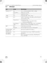
Utilizzo del terminale “AES/RE” (solo MT 350 PP, MT 550 PP)
I
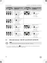
1. Far scorrere l’interruttore DIP (fig.
, pagina 3) nella posizione mostrata nella tabella
seguente per impostare la variante di collegamento.
Posizione
dell’interruttore
DIP
Programma di carica
desiderato
Posizione
dell’interruttore
DIP
Programma di carica
desiderato
Batterie al piombo-
acido (14,4 V) o
batterie AGM (14,4 V)
(fig.
• U1: 14,40 V
(0,5 – 4 h)
• U2: 13,45 V
Batterie al piombo-gel
(14,3 V)
(fig.
• U1: 14,30 V
(1,5 – 6 h)
• U2: 13,80 V
batterie AGM (14,7 V)
(fig.
• U1: 14,70 V
(0,5 – 3 h)
• U2: 13,50 V
Batterie LiFePO4
(13,9 V)
(fig.
• U1: 13,90 V
(0,5 – 1,5 h)
• U2: 13,90 V
Batterie LiFePO4
(14,4 V)
(fig.
• U1: 14,40 V
(0,3 – 1 h)
• U2: 13,8 V
Batterie LiFePO4
(14,2 V)
(fig.
• U1: 14,20 V (0,5 h)
• U2: 13,60 V
Batterie LiFePO4
(14,7 V)
(fig.
• U1: 14,70 V
(0,3 – 1 h)
• U2: 13,70 V
NOTA
La corrente di uscita massima del terminale “AES/RE” è 200 mA.

