background image


domat R560 

11/2018 Subject to technical changes. 

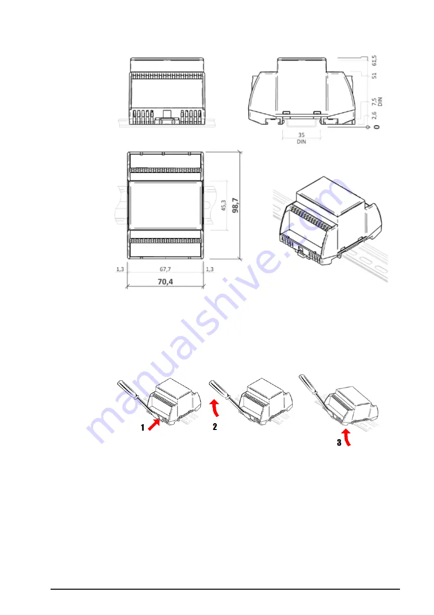
Dimensions 


Dimensions are in 

mm


Installation  

The R560 module is fixed on standard DIN rail (by snapping). 
 
When  removing  the  module  from  the  DIN  rail  proceed  as  follows:  Place  a 
screwdriver in the plastic slot which is in the middle  of bottom part of the module 
(1). Then push the screwdriver upwards (2). After that, the module can be removed 
by tilting it upwards (3). 


Addressing 

The Modbus address can be set as follows: 

-


hardwarewise:

 using DIP switches. The switches increase their bit weight 

from right to left, see image with example where address of 21 is set by 
activation of switches 4, 6, and 8 with bit weight of 16, 4, and 1 respectively.  
Valid settable range is 1 to 254. Address 0 (all switches OFF) means that the 
address is set as entered in the Modbus table. Address 255 (all switches ON) 
brings the module to INIT mode, where Modbus address is 1 and 
communication parameters are set to N, 8, 1, see image below. 
All changes apply after the module is switched off and on again. 

Summary of Contents for R560

Page 1: ... to 20 mA current measurement inputs if the corresponding DIP switch is activated The module communicates by means of RS485 data bus The Modbus RTU communication protocol ensures smooth and easy integration in a variety of control and data acquisition systems It connects to process stations PLCs directly or through the M012 interface RS485 to RS232 converter with galvanic isolation Removable conne...

Page 2: ...may be used for temperature measurement with Pt100 Pt1000 Ni1000 5000 and Ni100 6180 passive sensors Linearisation must be done in controllers Domat PLC for example just like at e g MCIO2 module In the R560 module there is recalculation to C for the Pt1000 sensor only Sampling 10 samples s Effective resolution 16 bit Measurement error The measurement deviation for all measured variables is 0 25 of...

Page 3: ...dication RUN orange LED system cycle OK LED flashes periodically 1 s ON 1 s OFF ERROR LED flashes in other pattern LED is still ON or OFF TxD red LED RS485 transmitting data at COM1 flashing transmitting data OFF no data traffic PWR green LED power supply ON power OK OFF no power applied weak or damaged power supply DIP switches ADR AUTO if all switches are OFF the address is used according to Mod...

Page 4: ... to technical changes domat R560 0 20 mA For current measurement 0 20 mA on individual channels switch the particular DIP switch to ON The 0 20 mA range must be also set over Modbus e g using Domat ModComTool Connection ...

Page 5: ... 3 Addressing The Modbus address can be set as follows hardwarewise using DIP switches The switches increase their bit weight from right to left see image with example where address of 21 is set by activation of switches 4 6 and 8 with bit weight of 16 4 and 1 respectively Valid settable range is 1 to 254 Address 0 all switches OFF means that the address is set as entered in the Modbus table Addre...

Page 6: ...s set to 0 All changes apply after the module is switched off and on again Safety note The device is designed for monitoring and control of heating ventilation and air conditioning systems It must not be used for protection of persons against health risks or death as a safety element or in applications where its failure could lead to physical or property damage or environmental damage All risks re...

Page 7: ...domat R560 11 2018 Subject to technical changes 7 Changes in versions 07 2017 First datasheet version 10 2017 Added measurement error value new image 02 2018 Added Safety note 11 2018 Minor changes ...

Reviews: