13 ENGLISH
1.
Press the lock-off lever, then pull the switch trig-
ger. The saw chain starts immediately.
2.
Push the front hand guard forwards with the back
of your hand. Make sure that the chain saw comes to an
immediate standstill.
►
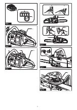
Fig.8:
1.
Front hand guard
2.
Unlocked position
3.
Locked position
Checking the run-down brake
CAUTION:
If the saw chain does not stop
within one second in this test, stop using the
chain saw and consult our authorized service
center.
Run the chain saw then release the switch trigger com-
pletely. The saw chain must come to a standstill within
one second.
Adjusting the chain lubrication
You can adjust the oil pump feed rate with the adjusting
screw. The amount of oil can be adjusted using the
universal wrench.
►
Fig.9:
1.
Adjusting screw
ASSEMBLY
CAUTION:
Always be sure that the tool is
switched off and the battery cartridge is removed
before carrying out any work on the tool.
CAUTION:
Do not touch the saw chain with
bare hands. Always wear gloves when handling
the saw chain.
Removing or installing saw chain
CAUTION:
The saw chain and the guide bar
are still hot just after the operation. Let them cool
down enough before carrying out any work on
the tool.
To remove the saw chain, perform the following steps:
1.
Pull the lever up while pressing its edge.
►
Fig.10:
1.
Lever
2.
Turn the adjusting dial to "-" direction to release
the saw chain tension.
►
Fig.11:
1.
Adjusting dial
3.
Turn the lever counterclockwise until the sprocket
cover comes off.
►
Fig.12:
1.
Lever
2.
Sprocket cover
4.
Remove the sprocket cover then remove the saw
chain and guide bar from the chain saw body.
To install the saw chain, perform the following steps:
1.
Make sure the direction of the chain. The arrow
mark on the chain shows the direction of the chain.
2.
Fit in one end of the saw chain on the top of the
guide bar and the other end around the sprocket.
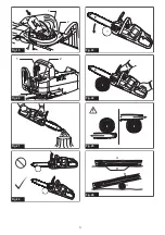
►
Fig.13:
1.
Sprocket
3.
Rest the guide bar in place on the chain saw.
4.
Turn the adjusting dial to "-" direction to slide the
adjusting pin in the direction of arrow.
►
Fig.14:
1.
Adjusting pin
5.
Place the sprocket cover on the chain saw so that
the adjusting pin is positioned in a small hole on the
guide bar.
►
Fig.15:
1.
Sprocket cover
2.
Guide bar
3.
Hole
6.
Turn the lever clockwise fully and a quarter turn
back to keep looseness for adjusting the chain tension.
7.
Turn the adjusting dial to adjust the chain tension.
8.
Turn the lever clockwise until the sprocket cover is
secured then return it to the original position.
►
Fig.16:
1.
Lever
2.
Sprocket cover
Adjusting saw chain tension
CAUTION:
Carry out the procedure of install-
ing or removing saw chain in a clean place free
from sawdust and the like.
CAUTION:
Do not tighten the saw chain too
much.
Excessively high tension of saw chain may
cause breakage of saw chain, wear of the guide bar
and breakage of the adjusting dial.
CAUTION:
A chain which is too loose can jump
off the bar and it may cause an injury accident.
The saw chain may become loose after many hours of use.
From time to time check the saw chain tension before use.
1.
Press and fully open the lever until it clicks. Turn it
counterclockwise a little to loosen sprocket cover lightly.
►
Fig.17:
1.
Lever
2.
Sprocket cover
2.
Lift up the guide bar tip slightly and adjust the
chain tension. Turn the adjusting dial to the "-" direction
to loosen, turn to the "+" direction to tighten. Tighten the
saw chain until the lower side of the saw chain fits in the
guide bar rail as illustrated.
►
Fig.18:
1.
Adjusting dial
2.
Guide bar
3.
Saw chain
3.
Keep holding the guide bar lightly and tighten the
sprocket cover. Make sure that the saw chain does not
loose at the lower side.
4.
Return the lever to the original position.
►
Fig.19:
1.
Lever
2.
Sprocket cover
Make sure the saw chain fits snugly against the lower
side of the bar.
OPERATION
Lubrication
Saw chain is automatically lubricated when the tool is in
operation. Check the amount of remaining oil in the oil
tank periodically.
To refill the tank, lay the chain saw on its side and
remove the oil tank cap. The proper amount of oil is 200
ml. After refilling the tank, make sure that the oil tank
cap is tightened securely.
►
Fig.20:
1.
Oil tank cap
2.
Oil tank (translucent)
Summary of Contents for AS3835
Page 2: ...Fig 1 2 1 17 3 4 5 6 11 13 15 12 18 7 8 10 16 9 14 Fig 2 1 2 3 Fig 3 1 2 Fig 4 2 ...
Page 3: ...1 2 Fig 5 1 Fig 6 2 1 Fig 7 2 3 1 2 3 1 Fig 8 1 Fig 9 1 Fig 10 3 ...
Page 4: ...1 Fig 11 1 2 Fig 12 1 Fig 13 1 Fig 14 2 1 3 Fig 15 2 1 Fig 16 1 2 Fig 17 2 3 1 Fig 18 4 ...
Page 5: ...2 1 Fig 19 1 2 Fig 20 Fig 21 Fig 22 Fig 23 Fig 24 Fig 25 A B A B Fig 26 5 ...
Page 7: ...1 2 Fig 35 30 1 5 1 Fig 36 Fig 37 Fig 38 Fig 39 2 1 Fig 40 1 2 Fig 41 1 2 Fig 42 7 ...


