15
UF 6925 / 30.08.17 en / 895
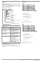
Function Diagram
0275136
Your Advantages
• For safety applications up to PL e / Cat. 4 e.g. SIL 3
• Space saving
• Connection front side
• Manual or automatic start
• Can be used also for safety gate
• Line fault detection on On-button
Features
• According to
-
Performance Level (PL) e and category 4 to EN ISO 13849-1
-
SIL Claimed Level (SIL CL) 3 to IEC/EN 62061
-
Safety Integrity Level (SIL) 3 to IEC/EN 61508 and IEC/EN 61511
• According to EN 50156-1 for furnaces
• 2-channel operation
• Forcibly guided output contacts
• With or without cross fault monitoring in the E-stop loop, switch S1
• Manual restart or automatic restart, switch S2
• LED indicator for channel 1, 2 and Netz
• Width 17,5 mm
Protection of people and machines
• Emergency stop circuits on machines
• Monitoring of position switches on a safety gate
The Emergency-Stop-Module UF 6925 is suitable to protect men and
machine by safety related enabling or disabling of a safety circuit. It is
used in applications with e-stop buttons and safety gates.
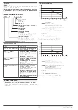
green LED Netz:
on when supply connected
green LED K1:
on when relay K1 energized
green LED K2:
on when relay K2 energized
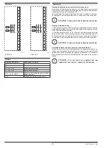
UF 6925.03
UF 6925.22
Block Diagrams
Indicators
Applications
Approvals and Markings
Product Description
Safety Technique
SAFEMASTER
Emergency Stop Module
UF 6925
emergency-stop
push button on
K2
K1
M11689
A1+ A2
S11
S12
S22 S33 S34
13 23
M11691
S21
14 24
K1
K2
K1
24V
K2
K2
K1
31
32
power
overvoltage and
short circuit protection
monitoring logic
A1+ A2
S11
S12
S22 S33 S34
13 23
M11693
S21
14 24
K1
K2
K1
power
24V
K2
K2
K1
33
34
overvoltage and
short circuit protection
monitoring logic
Canada / USA
All technical data in this list relate to the state at the moment of edition. We reserve the right for
technical improvements and changes at any time.


