background image

Original Operating Instructions 

Framax stripping corner I hydraulic

13

999239002 - 07/2018

Maintenance

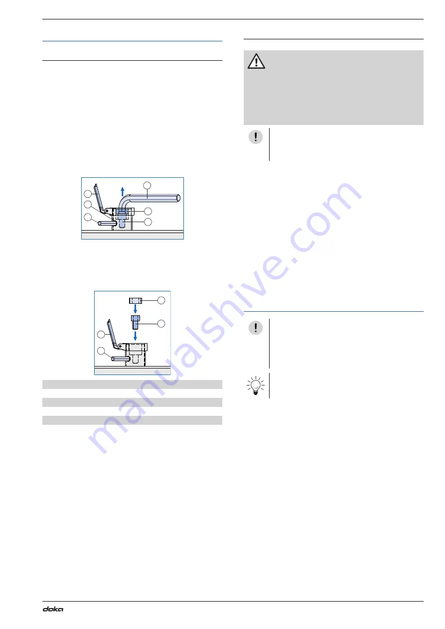
Changing the drive

Note:

The drive hexagon socket (width-across 8 mm) has to 

be replaced if it is damaged.
There are 3 spare cylinder screws M10x20 - 10.9 in the 

documents container.

Open the blue drive flap.

Insert the bit (width-across 8 mm) into the locking 

bore.

Loosen locknut (width-across 12 mm) with hexagon-

socket screw key (width-across 12 mm).

Remove cylinder screw M10x20 - 10.9 and replace it 

with a new cylinder screw M10x20 - 10.9.
Width-across, hexagon socket 8 mm

Retighten the locknut (width-across 12 mm).

Changing the oil

Unscrew the plug with a hexagon-socket screw key 

(width-across 5 mm).

Lift the unit on to a used-oil drum and drain the oil 

into the drum.

Re-seal the plug with Teflon tape, and screw it back 

in.

Open the screw at the oil filling opening.
Width-across 17mm

Refill the reservoir with approx. 3


litres of hydraulic 

oil (up to the maximum mark). Use 'Shell Tellus S2 

V15' hydraulic oil.

Re-seal the oil filling opening.

Dispose of the waste oil and soiled cleaning utensils 

correctly. Observe all relevant national laws.

Transport

A

Drive flap

B

Locking bore

C

Bit (width-across 8 mm)

D

Locknut (width-across 12 mm) (painted red

E

Hexagon-socket screw key (width-across 12 mm)

F

Cylinder screw M10x20 - 10.9 (drive hexagon socket (width-
across 8 mm)

F

A

9239-203-01

D

B

E

C

A

C

9239-203-02

F

D

CAUTION

Risk of burns or scalds if an oil change is 

attempted while the hydraulic oil is still hot!

If the hydraulic unit has been in operation for 

a lengthy period, allow the hydraulic oil to 

cool down before changing the oil.

Maximum oil temperature for oil changes: 

40°C.

NOTICE

Interval for oil change:

 ▪

once a year

NOTICE

Do not put the hydraulic unit on its side!
Putting the hydraulic unit on its side causes 

damage to the unit and leakage of hydraulic 

oil.

The handles or the strap can be used for trans-

porting the Hydraulic unit Framax V4.

Summary of Contents for 588614000

Page 1: ...0 Amstetten 999239002 07 2018 en GB The Formwork Experts Framax stripping corner I hydraulic 2017 models onward Original Operating Instructions Please retain for future reference by Doka GmbH A 3300 Amstetten 9239 200 01 ...

Page 2: ...draulic unit SCP V1200 50 60Hz Follow the directions in the User Information booklet of the formwork system that is being used Designation Framax stripping corner I hydraulic Max cylinder force 10000 kg 22000 lbs Year of manufacture see rating plate 9239 214 01 A C B A Adapter for Framax stripping corner I B Connecting pin 10cm C Spring cotter 5mm D Pair of hydraulic hoses 4 0m pre mounted on Fram...

Page 3: ...th Coupling adapter Framax stripping cylinder I intended use Boundary conditions for use Maintenance inspection Storage NOTICE Other use or use not in conformity with that stated above is non intended use and requires the prior written approval of the Doka company NOTICE The Framax stripping cylinder I is suitable for deployment at outside temperatures of between 5 C and 55 C Putting into service ...

Page 4: ...ed for installation It is not permissible to install the stripping cylinder on a stripping corner that does not have a hole for the locking pin This hole is a standard feature of all strip ping corners manufactured from 2005 onward To prevent abrasion or trapping damage the hydraulic hoses must be secured to the neighbouring formwork panel and properly laid and arranged Tight bending radii should ...

Page 5: ...necting pin 10cm 2 Back off the hexagon nut width across 41 mm by the desired difference 3 Extend the stripping cylinder until the Connecting pin 10cm can be reinstalled 4 Secure each Connecting pin 10 cm with a Spring cotter 5mm 5 Fully retract the stripping cylinder CAUTION Danger of crushing No body parts or objects between hydraulic cylinder and assembly plate A Spring cotter 5mm B Connecting ...

Page 6: ...cm Retract the stripping cylinder Switch off the hydraulic unit and disconnect the hydraulic hoses Lift the stripping cylinder clear Remove the adapter Position pins D17 5 in the adapter holes Pin the adapter into the stripping cylinder with Con necting pin 10cm and secure with Spring cotter 5mm Erecting Stripping Retract Framax stripping cylinder I Extend Framax stripping cylinder I 9239 200 02 9...

Page 7: ...Original Operating Instructions Framax stripping corner I hydraulic 7 999239002 07 2018 ...

Page 8: ...e the pegging tube from the fixing unit Place the spindle tube on the centring stud of the stripping corner Twist the spindle tube clockwise until fully engaged Push the pegging tube over the thread of the spindle tube Insert Connecting pin 10cm through the pegging tube and the Adapter for Framax stripping corner I and secure with Spring cotter 5mm Tighten the spindle nut against the pegging tube ...

Page 9: ...ramax stripping cylinder I Shown here with no guardrail system along the front Note Alternatively the shaft can be fitted with four Framax stripping cylinders I full complement A Framax stripping cylinder I B Framax stripping corner I C Hydraulic unit Framax V4 D Adapter for Framax stripping corner I C A D B B 9239 216 01 ...

Page 10: ...d requires the prior written approval of the Doka company Doka accepts no liability for products that have been altered Repairs may be carried out only by Doka or specialist companies authorised by Doka To avoid damage the drive components must be stored in such a way that they are protected against direct climatic influences and aggressive substances The hydraulic unit Framax V4 must be inspected...

Page 11: ...s Ensure scrupulous cleanliness during operation so that you can detect leaks at an early stage and rule out possible sources of errors Installation of the hydraulics Swivel the footplate flat to the ground Route the Pair of hydraulic hoses from the stripping cylinder to the Hydraulic unit Framax V4 and connect the hoses Temporarily stow pairs of hydraulic hoses that are not in use in the parking ...

Page 12: ...aulic hoses for Framax stripping cylinder I D Pair of hydraulic hoses f stripp cyl 5 00m optional CAUTION Wrist injury After extending or retracting the stripping cylinder switch off the cordless screwdriver and disengage it from the drive A Cordless screwdriver 18 V 1800 rotation min B Bit width across 8 mm C Drive hexagon socket width across 8mm D Maximum oil level E Minimum oil level C D B 9239...

Page 13: ...oss 17mm Refill the reservoir with approx 3 litres of hydraulic oil up to the maximum mark Use Shell Tellus S2 V15 hydraulic oil Re seal the oil filling opening Dispose of the waste oil and soiled cleaning utensils correctly Observe all relevant national laws Transport A Drive flap B Locking bore C Bit width across 8 mm D Locknut width across 12 mm painted red E Hexagon socket screw key width acro...

Page 14: ...or the stripping cylinder to be operated with the Hydraulic unit Xclimb 60 V45 50 60Hz Required system pressure 200 bar Follow the directions in the Hydraulic unit Xclimb 60 V45 50 60Hz Operating Instruc tions 9 20 2873 0 02 C C B D NOTICE Invariably only one stripping cylinder can be connected to and operated with the Hydraulic unit Xclimb 60 V45 50 60Hz Exception No one in the danger zone Formwo...

Page 15: ...he Hydraulic unit SCP V1200 50 60Hz A Flatface BG2 sleeve B Threaded coupling SKS BG3 connector C Threaded coupling SKS BG3 sleeve Follow the directions in the Hydraulic unit SCP V1200 50 60Hz Operating Instructions 92869 200 01 C D A B A C B NOTICE Invariably only one stripping cylinder can be operated with the Hydraulic unit SCP V1200 50 60Hz Exception No one in the danger zone Formwork erecting...

Page 16: ... pertinent fundamental health and safety stipulations of the relevant EC Direc tives The following harmonised standards were applied EN ISO 12100 2010 EN 349 1993 A1 2008 EN 982 1996 A1 2008 Person authorised to compile technical documentation pursuant to European Directive on Machinery Annex II Dipl Ing Ludwig Pekarek Josef Umdasch Platz 1 A 3300 Amstetten Amstetten 14 06 2018 Doka GmbH Josef Umd...

Page 17: ...amax V4 20 5 588981000 Hydraulikaggregat Framax V4 Hydraulic unit Xclimb 60 V45 50 60Hz 321 0 581322000 Hydraulikaggregat Xclimb 60 V45 50 60Hz System pressure controller Xclimb 60 V45 1 4 581329000 Systemdruckbegrenzer Xclimb 60 V45 Hydraulic unit SCP V1200 50 60Hz 2200 0 583102500 Hydraulikaggregat SCP V1200 50 60Hz Coupling adapter B Framax stripping cyl I 2 0 588982500 Kupplungsadapter B Frama...

Page 18: ...nd distributing formwork technology for use in all fields of the construction sector With more than 160 sales and logistics facilities in over 70 countries the Doka Group has a highly efficient dis tribution network which ensures that equipment and technical support are provided swiftly and profession ally An enterprise forming part of the Umdasch Group the Doka Group employs a worldwide workforce...

Reviews: