background image


Ordercode: 101602 

SB-804 Sender Box Pro 

Description of the device 


Features 

The SB-804 is a professional sender box from DMT. 


Input voltage: 85-264V AC, 50/60Hz 


Power consumption: 25W  


Patch LED screens without using a computer and LED Studio 


2x 802 Sendercard included 


Video input: 2x DVI-D + HDMI 


Use a digital video (DVI or HDMI) input and convert it, so that it can be sent through a single CAT5 
cable to your LED screen.  


Connections are made by Neutrik Ethercon connectors, ensuring a reliable connection in any 
situation. 


The SB-804 is the extended version of the SB-804 with two sender cards on board it's capable of 
configuring big led screen setups 


Equipped with 2 sending cards which are compatible with all DMT LED screens. 


With SB-804 you do not have to worry about which version LED Studio to use.  


Outputs to screen: 2x 2 Ethercon(RJ45) soft-patched connectors 


Power input: PowerCON IN/OUT 


Setup port: USB-B, RS 232 connection on the backside. 


The RS 232 is used for cascade screen brightness control: 16-levels adjustment on the front panel 


Resolutions: 640 x 480, 800 x 600, 1024 x 768, 1280 x 768, 1280 x 800, 1280 x 1024, 1366 x 768, 1440 x 900, 
1440 x 1080, 1600 x 576, 1600 x 900, 1600 x 1000, 1600 x 1200, 1680 x 1050, 1728 x 1296, 1920 x 1080, 
1920 x 1200, 2048 x 1152, 2048 x 1280, 2560 x 1440, 2560 x 1600, custom (only available in LED Studio 
software) 


Cooling: Cooling fan 


Standard rack size: 1U 


Dimensions:   482 x 358 x 44 mm (LxWxH) 

19 inch x 1HE (LxH) 


Weight: 2,88 kg 


This Senderbox does NOT have a scaling Function 


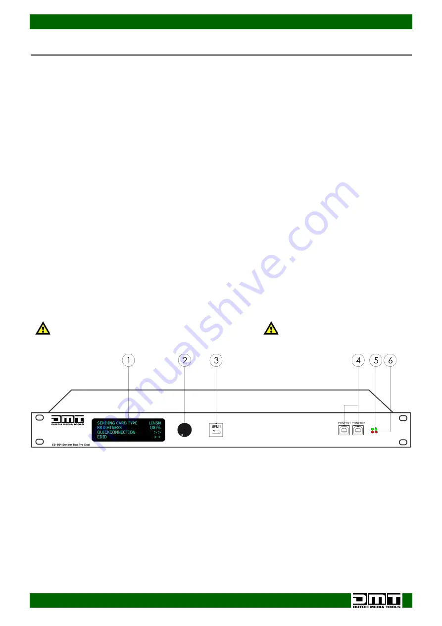
Frontside 


Fig. 01 


01)


LED display 

02)


Menu Control 

Turn the menu control to select and adjust your settings. Press the button to confirm. 

03)


Menu/ Back Button 

Press the button to go back by one step in the menu. 

04)


USB connector B for configuration via LED Studio Software 

05)


Green Signal LED 

Indicates if the unit is receiving a video signal.  
Flashing LED: video signal is present.  
LED OFF: No video signal 

06)


Red LED power indicator 

Indicates if the unit is switched ON. 


Summary of Contents for 101602

Page 1: ...SB 804 Sender Box Pro V2 Highlite International B V Vestastraat 2 6468 EX Kerkrade the Netherlands Ordercode 101602 MANUAL ENGLISH ...

Page 2: ... No 1 2 9 1 3 Output Format 9 1 4 Quick Connection 10 1 4 1 Sending Card Set 10 1 4 2 Receiving Card Set 10 1 5 Cascade 11 1 6 Brightness 11 2 SENIOR 11 2 1 Receiving card Separate 11 2 2 Color Temperature 11 2 3 Edid 11 2 4 Gamma SET 11 2 5 System Info 12 3 FACTORY RESET 12 Quick LED Screen Setup 13 Working with the U and D ports 15 Sender Card resolutions 18 Installation LED Studio Software 19 L...

Page 3: ...nt includes SB 804 Sender Box Pro with PowerCON power cable 1 5 m 802 LINSN onboard sending card User manual Safety Instructions Every person involved with the installation operation and maintenance of this system has to be qualified follow the instructions of this manual Before you initial start up please make sure that there is no damage caused by transportation Should there be any consult your ...

Page 4: ...nspect for safety before operating If the device has been exposed to drastic temperature fluctuation e g after transportation do not switch it on immediately The arising condensation water might damage your device Leave the device switched off until it has reached room temperature If your DMT device fails to work properly discontinue use immediately Pack the unit securely preferably in the origina...

Page 5: ... always a safe method to use Note If you are given an RMA number please include the following information on a piece of paper inside the box 01 Your name 02 Your address 03 Your phone number 04 A brief description of the symptoms Claims The client has the obligation to check the delivered goods immediately upon delivery for any short comings and or visible defects or perform this check after our a...

Page 6: ...CON IN OUT Setup port USB B RS 232 connection on the backside The RS 232 is used for cascade screen brightness control 16 levels adjustment on the front panel Resolutions 640 x 480 800 x 600 1024 x 768 1280 x 768 1280 x 800 1280 x 1024 1366 x 768 1440 x 900 1440 x 1080 1600 x 576 1600 x 900 1600 x 1000 1600 x 1200 1680 x 1050 1728 x 1296 1920 x 1080 1920 x 1200 2048 x 1152 2048 x 1280 2560 x 1440 ...

Page 7: ...rd CAT5 or CAT6 cable with or without the Ethercon connector 09 Audio Input 10 DVI video IN 11 HDMI IN Does NOT have DHCP Connect the image signal from the computer 12 Ground Earth connection 13 Power switch ON OFF 14 Neutrik PowerCON OUT 85 264V AC 15 Neutrik PowerCON IN 85 264V AC Do not HOT plug HDMI or DVI Turn OFF your device before connecting any cables Otherwise your device can become damag...

Page 8: ...ways disconnect from electric mains power supply before cleaning or servicing Damages caused by non observance are not subject to warranty Set Up and Operation Follow the directions below as they pertain to your preferred operation mode Before plugging the unit in always make sure that the power supply matches the product specification voltage Do not attempt to operate a 120V specification product...

Page 9: ...8 Ordercode 101602 SB 804 Sender Box Pro Menu Overview At start up the device will show ...

Page 10: ...ding Card Type 01 You cannot change or enter this menu 1 2 Sending Card No 1 2 With this menu you can you can set which sending card you want to use 01 Turn the control 02 to select SENDING CARD and press the control 02 to enter 02 Turn the control 02 clockwise or counter clockwise to change the sending card from 03 Press the control 02 to confirm changes 1 3 Output Format 01 Turn the control 02 t...

Page 11: ...he parameters values 04 Once you have adjusted the settings turn the control 02 to select SAVE TO SENDER CARD and press the control 02 to confirm 1 4 2 Receiving Card Set 01 Turn the control 02 to select RECEIVING CARD SET then press control 02 to enter the menu 02 Turn the control 02 to set the parameters values 03 The available 9 options are CHOOSE CABLE PORT D or PORT U HORIZONTAL CARD the numb...

Page 12: ...ol 02 to enter the menu 02 Turn the control 02 to set the parameters values 03 The available 5 options are Choose Cable Port A Port B Receiving card No 1 256 X and Y positions for the receiving card SEND TO RECEIVER once you have set the X and Y positions you can send them to the receiver 2 2 Color Temperature 01 Turn the control 02 to select SENIOR then press control 02 to enter the menu 02 Turn ...

Page 13: ...ON view the sending card version RECEIVING CARD VERSION view the receiving card version SOFT VERSION view the currently installed software version 3 FACTORY RESET 01 Press the control 02 to enter the menu 02 Turn the control 02 clockwise or counter clockwise to Rest SEL or don t reset NO Once have chosen the desired option press the control 02 to reset or the MENU button 03 to return to the previo...

Page 14: ...MENU button 03 to enter the main menu 05 Turn the control 02 to select QUICK CONNECTION in the main menu and press the control 02 to enter 06 Turn the control 02 to select QUICK CONNECTION again and press the control 02 to enter 07 Turn the control 02 to select RECEIVING CARD SET and press the control 02 to enter 08 09 Turn the control 02 to select CHOOSE CABLE press the control 02 and turn the co...

Page 15: ...02 to select CONNECT CARD TYPE 15 Press the control 02 to enter Connection Mode is the routing of your data line Always seen from the front of your LED screen 16 Turn the control 02 to select CONNECTION MODE and press the control 02 to enter 17 Turn the control 02 to choose one of the 8 ways in which the LED screens are connected with the main data cable 18 Press the control 02 to confirm your cho...

Page 16: ...witch the Sender Box Pro ON 04 Turn the control 02 to select QUICK CONNECTION in the main menu and press the control 02 to enter 05 Turn the control 02 to select QUICK CONNECTION again and press the control 02 to enter 06 Turn the control 02 to select RECEIVING CARD SET and press the control 02 to enter 07 Turn the control 02 to select CHOOSE CABLE press the control 02 and turn the control 02 to s...

Page 17: ...control 02 to confirm your choice 18 Turn the control 02 to select SEND TO RECEIVER and press the control 02 to confirm 19 Turn the control 02 to the left to return to the previous menu screen 20 Turn the control 02 to select CHOOSE CABLE press the control 02 and then turn it to set the output D port 21 Turn the control 02 to select HORIZONTAL VERTICAL CARD how many horizontal and vertical LED scr...

Page 18: ... 26 Turn the control 02 to select CONNECT CARD TYPE and press the control 02 to enter 27 Turn the control 02 to select CONNECTION MODE press the control 02 and then turn it choose one of the 8 ways in which the LED screens are connected with the main data cable 28 Press the control 02 to confirm your choice 29 Turn the control 02 to select SEND TO RECEIVER and press the control 02 to confirm ...

Page 19: ...e 13 1344 480 645120 1 cable 14 1280 512 655360 1 cable 15 1216 512 622592 1 cable 16 1152 512 589824 1 cable 17 1088 512 557056 1 cable 18 1024 640 655360 1 cable 19 896 640 573440 1 cable 20 832 640 532480 1 cable 21 768 640 491520 1 cable 22 704 640 450560 1 cable 23 640 640 409600 1 cable 60HZ output TS802 D support capability No Max support Note Width Height Total 1 2048 640 1310720 2 cables ...

Page 20: ...o Software Do NOT download the LED Studo software from other sites LED Studio Software Serial Code 888888 01 Double click to open the installation file of LED Studio software 02 A small window will open and you will have to select the preferred language 03 Click on Next 04 Fill in the requested information Username Company Name and Serial Code 888888 ...

Page 21: ...20 Ordercode 101602 SB 804 Sender Box Pro 05 Click on Next 06 Select the destination folder and click on Next 07 Click on Next ...

Page 22: ...21 Ordercode 101602 SB 804 Sender Box Pro 08 Click on Next 09 Click on Next 10 Installation is now complete ...

Page 23: ... LED screen It communicates with the sender card inside the SB 804 via the CAT 5 data cable The LED Studio software is Windows native If you use Mac OS use Bootcamp and the Windows License 01 After opening the main window of the LED Studio please go to Option menu and click on Software Setup 02 Enter the Software Setup screen ...

Page 24: ...ce you have inserted the correct password the following hardware setup appears on the screen Sender Setup First click Default to reset the sender card in the senderbox You will return to the factory default setting Then click Save on sender to save your settings If the pixel size of your LED screen see Display mode is not larger than 1024x768 your settings are OK Make sure that the display resolut...

Page 25: ...Connect your computer to the Sender Box via USB 03 Power on the Sender Box and start the LED Studio software 04 Go to Option menu and click on Software Setup 05 Enter the screen of software setup 04 When the Software Setup window appears on the screen just type in linsn Note no dialog box will appear on the screen to type it in 05 After this a pop up window appears on the screen requesting a passw...

Page 26: ...of LED screens which we want to control 01 We can do this by entering the number of LED screens in our Display connection panel 02 First enter how many screens are to be used horizontally Horizontal card and vertically Vertical card As an example we have chosen 4 x 3 LED screens 4 Width 3 Height 03 After setting up the number of LED screens the display will show ...

Page 27: ...rder No to 1 06 Please make sure to select the proper main cable 1 No sender U cable 07 Set width and height per LED screen this information can be found in the specifications from your LED screen When it is set click on the first block The information will turn green 08 Now use the arrow keys on your keyboard to jump to the next LED screen in your setup ...

Page 28: ...27 Ordercode 101602 SB 804 Sender Box Pro 09 Click on Send to receiver The display will show 10 The data will be uploaded to the receiver 11 Click on Ok when the procedure is finished ...

Page 29: ...28 Ordercode 101602 SB 804 Sender Box Pro 12 The display will show 13 Now Save to receiver button will become active 14 Click on Save to receiver 15 The data will now be saved to the receiver ...

Page 30: ...29 Ordercode 101602 SB 804 Sender Box Pro 16 After that the display will show 17 Click on Ok The procedure is finished ...

Page 31: ...device or parts of the device have to be tightly connected and must not be corroded 02 There may not be any deformations on housings fixations and installation spots 03 Mechanically moving parts like axles eyes and others may not show any traces of wearing 04 The electric power supply cables must not show any damages or material fatigue Troubleshooting This troubleshooting guide is meant to help s...

Page 32: ... have to worry about which version LED Studio to use Setup port USB B RS 232 connection on the backside The RS 232 is used for cascade screen brightness control 16 levels adjustment on the front panel Cooling Cooling fan Video input 2x DVI D HDMI Power input PowerCON IN OUT Outputs to screen 2x 2 Ethercon RJ45 soft patched connectors 2x 802 Sendercard included Resolutions 640 x 480 800 x 600 1024 ...

Page 33: ...32 Ordercode 101602 SB 804 Sender Box Pro ...

Page 34: ...33 Ordercode 101602 SB 804 Sender Box Pro ...

Page 35: ...34 Ordercode 101602 SB 804 Sender Box Pro ...

Page 36: ... 2016 D M T ...

Reviews: