background image


Chapter 3                                                                                                                     25 


Touch 

  on 

Gain 

to  change the  gain  level (signal  sensitivity).  The 

higher the gain the more sensitive the unit will be making it easier to 
measure  lower  thickness  values.  But  excessive  gain  can  also  cause 
erroneous measurements.  
The gain is typically adjusted when changing transducers.  
 

Touch the 

-

 keys to adjust the gain 

value and touch 

 to save and exit.  

 
Touch 

 to exit without making changes.  


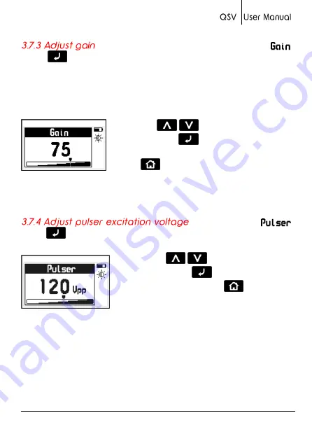
Figure 3.18: Adjust gain level 


Touch 

 on 

Pulser

 to adjust the transducer pulser excitation level. 


Touch  the 

-

  keys  to  adjust  the 

tension and touch 

 to save and exit. To 

exit without changes touch 


Figure 3.19: Transducer pulser excitation tension editor screen 

 
Considerations when adjusting the pulser excitation tension: 
 
Higher  excitation  levels  mean  that  more  energy  is  applied  to  the 
emission crystal in the transducer which allows for better penetration 
in high attenuation and large or thick materials. 
  

Summary of Contents for QSV-B

Page 1: ......

Page 2: ...P N QSD 101 ENG Rev 2 2012 ...

Page 3: ...ing screen 9 2 2 Keys in the measuring mode 10 2 3 Zero calibration Auto 12 2 4 Measuring the material velocity 13 2 4 1 Measuring velocity with the caliper connected to the unit 13 2 4 2 Measuring velocity using a known thickness value 14 2 5 Measuring thickness with a known velocity 15 Chapter 3 Menu system and editing 3 1 Instructions on using the menu system 16 3 2 Main menu 17 3 3 Change meas...

Page 4: ... 3 7 3 Adjust gain 25 3 7 4 Adjust pulser excitation voltage 25 3 7 5 Set auto off time 26 3 7 6 Adjust display contrast 26 3 7 7 Beep activation 27 3 7 8 Hold last value 27 3 7 9 Model upgrade licenses 28 3 7 9 Unit information 30 Tips on how to measure correctly Technical specifications Additional information Unit maintenance QSV accessories Error messages Our website www demeq com Technical sup...

Page 5: ...ry to build instruments that are robust precise and easy to operate We are convinced that our products would not be complete without permanent technical and after sales support So in addition to a great product we offer Quick answers to your inquiries Unlimited access to technical information as well as application notes Special offers for registered customers Firmware and software upgrades at no ...

Page 6: ...o responsibility as a result of the improper use of our instruments ASTM E797 The user must be trained in ultrasonic testing procedures and on how to properly configure the unit for testing All of the following should be taken into consideration Understand the theory on sound wave propagation Select the transducer that is best suited for your application Know the specific requirements for the test...

Page 7: ...s with dual crystal transducers that use the pitch catch principal Dual crystal transducers use two piezoelectric crystals whereby one crystal is excited with short electrical pulses from the unit sending short acoustic waves into the test piece The second crystal then receives the acoustic waves reflected at the end of the test piece The frequency of the acoustic waves changes between 2 and 10 MH...

Page 8: ... calibrated incorrectly the resulting measurements will be unreliable Each and every time a transducer is changed it must be calibrated to the unit Because the sound velocities in materials will often vary significantly from published values best results are obtained when the instrument is calibrated on a reference test block made from the same material as that of the actual test piece The block s...

Page 9: ...hould be kept to a minimum and consistent pressure should be applied on the transducer when measuring Doubling refers to a thickness measurement that displays a reading that is twice or even three times the real test piece thickness Doubling often may happen when trying to measure below and above the specified range for the transducer and when using worn transducers When in doubt the test piece th...

Page 10: ...rolled instruments always make sure that the operations required for your application are in correct working order Demeq S R L provides a limited warranty for a period of 2 two years on electronic units and for 6 six months on transducers from the date of purchase and may be extended for up to 5 years Every instrument undergoes thorough testing during manufacturing as well as before shipping In th...

Page 11: ...aphic LCD display with LED backlight illumination 2 Move Left key 3 Move Up key 4 Menu key Enter and exit measure screen Exit and return to menus Home 5 Enter key Edit values on the measure screen Edit 6 Move Down key Manually store a value Store ...

Page 12: ...ng center point lock and unlock keypad on measure screen 11 Vertical scrolling center point adjust LCD contrast Figure 1 2 Unit connectors 1 Receiving transducer connector Type Lemo 00 2 Emitting transducer connector Type Lemo 00 3 USB mini connector to connect to PC using a USB cable supplied with the unit This same USB connector is also used to connect the digital caliper interface so that the c...

Page 13: ...figure 1 3 1 and gently push the extraction ribbon upward and slightly towards the right to release the batteries figure 1 3 2 When you install new batteries first insert the positive end of each battery so that it coincides with the positive pole inside the battery compartment as you see in figure 1 4 1 Always leave the extraction ribbon underneath the batteries Figure 1 3 Removing batteries ...

Page 14: ...ace Insert batteries Notes Use new alkaline top brand batteries only Do not mix new and old batteries Always replace both batteries Rechargeable batteries type NiMH can be used but will result in less time of continuous operation ...

Page 15: ...al probes you could basically connect any probe to your QSV Keep in mind that the gain may need to be adjusted when changing probes To connect the probe simply align any of the male connectors located at the end of the transducer cable to any of the female connectors located on the gauge and press gently until connected To release the probe hold the knurled section on the male connectors and pull ...

Page 16: ... seconds to shutdown the unit With the unit on making short touches to the will activate special functions described in later chapters of this manual Backlight illumination and contrast options can be changed from any screen in the unit Touch to change the backlight illumination settings Figure 1 6 Backlight illumination options ...

Page 17: ... 7 Display contrast adjustment To lock the keypad place your finger on the white dot located in the center of the horizontal scrolling bar between the keys Move your finger to the right following the dotted line and a window on the unit display will open with the word Lock Continue moving your finger in the same direction until you enter locked mode The window on the display will close and the loc...

Page 18: ...8 Chapter 1 Sliding the finger to the left will unlock the keypad Figure 1 9 Unlocking the keypad Important The keypad can only be locked and unlocked in the measuring screens ...

Page 19: ...as stored 2 Locked keypad icon indicator Page 8 3 Inactive calibration disk indicator Page 16 4 Coupling level indicator 5 Unit 6 Battery level Indicator 7 Minimum measured value 8 Velocity measured in the unit that you selected 9 Thickness of the test piece being measured ...

Page 20: ... of velocity and thickness Touch to select velocity Toque to select test piece thickness Always use the keys to edit the values in any given field and touch to save Figure 2 2 Measuring screen in select edit mode Notes The velocity field can only be edited if an actual measurement was taken If the velocity is 0 this field cannot be edited When a measurement was taken and the velocity is changed a ...

Page 21: ...ure 2 3 Figure 2 3 Materials velocity list table Use the keys to scroll the list and touch to select or touch to exit and return to the edit velocity field With a short touch the minimum measured value is reset to 0 Touch for 2 or more seconds to shutdown the unit Changes the backlight illumination Adjust display contrast Lock and unlock the keypad ...

Page 22: ...h is the default material velocity used in this calibration method Tip In order to measure the thickness of the calibration disk without activating the automatic calibration procedure simple touch the edge of the disk until an icon appears as shown in Figure 2 1 3 Inactive calibration disk indicator Page 9 While still touching the edge of the disk couple the transducer to obtain its thickness meas...

Page 23: ...hickness with the caliper connected to the QSV The value in the caliper will appear in the unit display Touch the key to save the thickness value from the caliper to the unit At this point in time changing the thickness value of the caliper will no affect the saved measurement Measure the sound velocity placing the transducer on the exact same place where the thickness measurement was taken with t...

Page 24: ...he following Measure the material for which you already know the thickness Lift the transducer and touch to enter the Select Edit mode Touch to edit the thickness measurement field Use the cursors to set the velocity and touch to confirm or touch to cancel When editing the thickness value observe that the velocity will change accordingly Note When changing the material velocity using a known thick...

Page 25: ... enter the Select Edit mode Touch to edit the velocity field Use the cursors to set the velocity and touch to confirm or touch to cancel Tips Touch the when editing velocity and a screen will appear with the most commonly used materials and their velocities Use the cursor keys to scroll the list and touch to select or touch to exit and return to the edit velocity field ...

Page 26: ...eys When you reach the end of the menu and move to the next menu option it becomes circular as shown below Figure 3 1 Example of how a circular menu works To select a menu option touch and to exit and return to the previous menu touch To go to the measuring screen touch from the main menu Figure 3 2 The Home key from the measuring screen ...

Page 27: ...ed in the following items Touch on Unit in the main menu to open the list of available units Use the keys to scroll the menu Touch to select the unit and touch to save and exit this menu Figure 3 4 Units menu The QSV has high and low alarms that alert the operator when the measurement is greater than the value set for the high alarm and or when the measurement falls below the value set for the low...

Page 28: ...en Visible alarm that causes measurements to be displayed in dotted instead of regular numbers Light Visible alarm that activates the display backlight illumination causing it to flash Select Memory from the main menu to view all menu options for the Data logger The QSV can store up to 5000 values that can be viewed on the unit display and or transferred to a PC via USB using dmq DataCenter Figure...

Page 29: ...nit memory will appear in DataCenter To view their contents simply double click on each file For additional information on dmq DataCenter software refer to the manual included in the CD that you received with your QSV or download the manual at http www demeq com Download html Touch on View Data to view the contents of the file Touch to exit the file Figure 3 8 File view in a grid format The QSV st...

Page 30: ...yed asking you to confirm or to cancel this action Touch to cancel and return to the previous menu or touch to begin deleting all files Figure 3 9 Erase All confirmation screen When the erase all action has been confirmed the following screens will be displayed Figure 3 10 Erase All progress screens After this process is completed all of the cells in the grid will be empty ...

Page 31: ... key to store values Auto When the transducer is coupled measurements are continuously stored Free memory is followed by a number representing the remaining memory that is available to store data and is represented in number of cells Touch on Free to view the remaining number of free cells and the free memory space as a percentage of the unit total memory Figure 3 12 Remaining memory screens ...

Page 32: ... menu In Auto Thickness mode the measurements that you take with the caliper are automatically saved to the unit until the transducer is coupled To enable this option touch A caliper can only be used with the QSV DLC model To connect the caliper to the QSV electronic unit use the interface cable provided with the unit and connect one end of the cable to unit and the other end to the caliper Figure...

Page 33: ...to open the general configuration options menu for the QSV that includes measurement related settings such as Gain and other more general settings such as Keypad Sensitivity and AutoOff time Figure 3 15 General configuration options menu Touch on Language which is also identified with a flag to view available language options Use the cursor keys to scroll available language options and touch to se...

Page 34: ...irm the change in sensitivity touch If you touch any other key or the counter that appears on your screen reaches 0 0 the sensitivity will return to its previous setting The factory default setting is 50 Under special conditions we suggest that the sensitivity level be changed Tips If the unit will be operated using security gloves we recommend that the sensitivity level be raised To make the keyp...

Page 35: ...save and exit Touch to exit without making changes Figure 3 18 Adjust gain level Touch on Pulser to adjust the transducer pulser excitation level Touch the keys to adjust the tension and touch to save and exit To exit without changes touch Figure 3 19 Transducer pulser excitation tension editor screen Considerations when adjusting the pulser excitation tension Higher excitation levels mean that mo...

Page 36: ...e set to higher tensions The unit will shutdown automatically if no key is touched or no measurement is made when you set the auto off time Touch on AutoOff to set the time before the unit automatically shutdown Touch the keys to set the time and touch to save and exit Touch to exit without making changes Figure 3 20 AutoOff time Use this setting to adjust the screen contrast making it lighter or ...

Page 37: ...ture in order to maintain optimal viewing conditions Beep refers to the sounds that the unit makes when keys are touched and when the audible alarm is activated Touch to enable or disable the beep option When you enable the Hold last option the last measured value will be displayed on the unit screen even when the transducer is not coupled When hold last is disabled and the transducer is not coupl...

Page 38: ...r to purchase a license you must provide all of the following information Unit model Unit serial number The type of license that you would like to purchase Touch on Licenses to view all licenses available for your unit active licenses are indicated with checkmarks To enter the new license number that you purchased from dmq touch or to exit and return to the previous menu touch Figure 3 23 License ...

Page 39: ... After entering your new license number the unit will respond with one of the following messages Figure 3 25 Response messages after a license is entered If the license number that you entered is correct the unit will show an updated license screen that will include your newly activated license now followed by a checkmark ...

Page 40: ...r 3 Touch on Unit Info to view the hardware and software versions in your unit To view different unit information screens touch the keys To return to the main menu touch Figure 3 26 QSV unit information screens ...

Page 41: ...ated in the front of the unit particularly when changing transducers Know the velocity of the material you will be measuring or have a reference test piece made of the same material you will be measuring and of a known thickness value so that you can precisely determine the material velocity based on its thickness Gain levels are set from factory with the optimal values that correspond to the tran...

Page 42: ...in Calibration Auto 1 Point Alarms Minimum Audible and visual Languages English Spanish Portuguese Data logger Up to 5000 values Manual and Continuous capture modes View data in grid or graphic formats Display Graphic LCD 128 x 64 pixels with LED backlight illumination and digital contrast adjustment Keypad Touch sense with no mechanical parts and sensitivity adjustment Battery life 100 hours with...

Page 43: ... substances Do not clean the unit with solvents Do not leave the unit display exposed to direct solar light for prolonged periods of time as this could damage the display Remove the batteries if the unit will be stored for an extended period of time Remove the transducer using the connectors and not the cable Do not twist or strangle transducer cable Do not expose the unit to temperatures below 10...

Page 44: ...ace cable QSS 201 2Mhz transducer 15 mm diameter QSS 501 5Mhz standard transducer 10 mm diameter QSS 701 7Mhz transducer 5 mm diameter QSR 161 6 step calibration block mm QSR 141 4 step calibration block in QSG 001 Coupling gel small QSG 002 Coupling gel large QAC 002 RS232 cable to connect to a PC QAC 003 RS232 cable to connect to a printer ...

Page 45: ... Figure A 2 System error message Error 1 Internal Error Cause Internal Error Solutions Shutdown the unit wait a few seconds and power back on Contact dmq Error 2 Attempt to store a value over an existing value Cause Improper unit shutdown Example Removing batteries and powering the unit back on to store values in the Data Logger Solution Download Data Logger values to PC or printer and erase memor...

Page 46: ... it relates to your QSV including Application notes Manuals and brochures New accessories Our service department is committed to providing prompt and courteous service Should you encounter any issues with your QSV please send us a detailed description of your problem to www demeq com form_Support html ...

Page 47: ...P N QSD 101 ENG Rev 2 2012 2012 dmq ...

Reviews: