19
eng
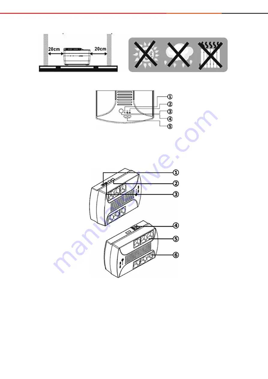
Figure 1. UPS location
Figure 2. Top view. Buttons and LEDs on the front side of the UPS
1. Network led (green)
2. Battery charge led (yellow)
3. Battery mode led (red)
4. On/off button
5. USB - memory inputs
Figure 3. Side view. Buttons, LEDs and connectors on the side of the UPS
1. USB (optional)
2. RJ11 (optional)
3. RS232 (optional)
4. AC input
5. Redundant output connector (if there is no voltage at the UPS input,
the load connected to this output will receive power supply from the UPS batteries)
6. Output connector without redundancy (if there is no voltage at the UPS input,
the load connected to this output will be disconnected)


