v.220629 | 15
COMPONENTS
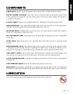
DRAIN VALVE: Used to drain condensation from the air tank. Located at bottom of tank.
MOTOR THERMAL OVERLOAD: The motor has an automatic thermal overload protector. If the
motor overheats, this protector will shut off the motor. The motor must be allowed 30 minutes to
cool before restarting.
QUICK-CONNECT: Offers a quick release feature for attaching and removing the air hose.
PRESSURE SWITCH: This controls the power to the motor and also the cut-in/cut-out pressure
settings. This switch serves as the Auto-On/Off positions for the unit.
AIR INTAKE FILTER: Provides clean air to the pump and must always be kept free of debris.
Check on a daily basis or before each use.
AIR COMPRESSOR PUMP: Oil free direct driv¬en pump that compresses air, which is distributed
to the tank.
CHECK VALVE: When the pump is not in operation the valve closes to retain air pressure inside
the tank.
PRESSURE RELIEF VALVE: The pressure relief valve located on the side of the pressure switch
is designed to automatically release compressed air when the air compressor reaches cut-out
pressure. The release air should only escape momentarily and the valve should then close.
TANK SAFETY VALVE: Used to allow excess tank pressure to escape into the atmosphere. This
valve should only open when the tank pressure is above the maximum rated pressure.
OUTLET PRESSURE GAUGE: Indicates the outgoing air pressure to the tool and is controlled by
the regulator.
TANK PRESSURE GAUGE: Indicates the reserve air pressure in the tank.
REGULATOR: The regulator controls the air pressure coming from the air tank. To increase the
pressure, turn the knob clockwise and to decrease the pres¬sure turn the knob counter-clockwise.
LUBRICATION
This is an oil-free product and DOES NOT require lubrication to operate.
ENGLISH
Summary of Contents for AC20G
Page 5: ...SECTION I SAFETY ...
Page 11: ...SECTION II INSTALLATION ...
Page 14: ...SECTION III OPERATION ...
Page 18: ...SECTION IV MAINTENANCE ...
Page 22: ...SECTION V PARTS SCHEMATICS ...
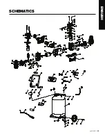
Page 25: ...v 220629 25 SCHEMATICS ENGLISH ...
Page 30: ...SECTION I SÉCURITÉ ...
Page 37: ...SECTION II INSTALLATION ...
Page 40: ...SECTION III FONCTIONNEMENT ...
Page 44: ...SECTION IV ENTRETIEN ...
Page 48: ...SECTION V PIÈCES ET SCHÉMAS ...
Page 51: ...v 220629 51 SCHÉMAS FRANÇAIS ...
Page 52: ......


