background image

Adjusting the Blade Guard

The blade guard protects against unintentional 

contact with the saw blade and from chips flying 

about. In order for the upper blade guard to 

provide adequate protection against contact with 

the band saw blade, it must always be set as close 

as possible against the workpiece 

(max. distance 3 mm).

1. Loosen the locking knob.

2. Rotate the setting knob to adjust the blade 

guard in the right position, then fasten the locking 

knob.

12. Operation

Mounting the saw in the stable and flat 

supporting surface

1. Drill 4 holes in the supporting surface.

2. Put fixing bolts through the base plate and 

secure with nuts.

ON/OFF Switch

The saw can be switched on by pressing the 

green pushbutton.

The red pushbutton has to be pressed to switch 

off the machine.

10

Start the saw only after the following 

preparations are completed:

● The saw is fastened; 

● The saw table is installed and    

aligned;

● Safety devices have been checked. 

Connect the saw to the mains supply 

only after all of the above preparations 

are completed! Otherwise there is a 

risk of an unintentional starting of the 

saw, which can cause severe personal 

injury.

Summary of Contents for DJMBAS80

Page 1: ...Band Saw Item No DJMBAS80 Band Saw Original Operating Manual ...

Page 2: ...e reliability and service life of the machine In addition to the safety regulations in the operating instructions you have to meet the applicable regulations that apply for the operation of the machine in your country Keep the operating instructions package with the machine at all times and store it in a plastic cover to protect it from dirt and moisture Read the instruction manual each time befor...

Page 3: ...2 ...

Page 4: ...r safety goggles or safety glasses with side shields when operating Wear appropriate hearing protection Wear respiratory protection to avoid the risk of inhaling harmful dust Always keep hands and feet away from all moving parts during operation Moving parts can cut or crush body parts Always keep hands and feet away from all pinch points Do not touch parts that might be hot from operation Allow p...

Page 5: ...ontact with the blade in the uncovered cutting zone Injuries cuts when changing the blade Injury from catapulted workpieces or parts of work pieces Crushed fingers Kickback Tilting of the workpiece due to inadequate support Touching the blade Take care of your tools Keep cutting tools sharp and clean in order to be able to work better and more safely Follow the instructions for lubrication and for...

Page 6: ...pecifications Mains Voltage 240V 50Hz Power 250W Throat Capacity 195 mm Max Cutting Height 80 mm 90 45 mm 45 Blade Wheel Dia 205 mm Blade Length 1400 mm Blade Width 3 5 12 mm Cutting Speed 950 m min Table Size 302 304 mm Table Tilt 90 45 6 Contents Supplied The band saw comes partially assembled and is shipped in carefully packed carton After all the parts have been removed from the carton you sho...

Page 7: ...able has to be pulled off the reel Persons working on the machine should not be distracted Note the direction of rotation of the motor and blade Never cut workpieces which are too small to hold securely in your hand For straight cuts of small workpieces against the longitudinal limit stop the push stick has to be used Never operate the machine if either the door protecting the blade or the detacha...

Page 8: ... with three nuts M6 and three fla t washers 5 Attach two screws and two knurled nuts with U shape block that were removed in step one and fasten Push Stick 1 Fix the screw and nuts on the machine leaving room for push stick 2 Hang the push stick on the screw Rip Fence Clamp the rip fence It can be used on both sides of blade 1 2 Work Table Table Insert NOTE Before fastening the work table make sur...

Page 9: ...er on the rubber tyres of the band saw wheels Turning the setting knob clockwise increases the blade tension Turning the setting knob counter clockwise reduces the blade tension Adjusting the Work Table Tilting After loosening both locking screws the work table tilts steplessly through 45 to the blade Locker 1 2 M4 25 2 M4 16 1 M4 16 1 B M4 25 2 During installation do not get the cables crushed by...

Page 10: ...to the front It can be used on both sides of the blade Work Table Alignment Saw Table Lateral Alignment 1 Loosen the three fastening screws that hold the lower table trunnion 2 Align working table so that the blade runs through the centre of the table insert s slot 3 Tighten the three fastening screws again Aligning the work table at right angles to the blade 1 Raise upper blade guide fully Check ...

Page 11: ...n Mounting the saw in the stable and flat supporting surface 1 Drill 4 holes in the supporting surface 2 Put fixing bolts through the base plate and secure with nuts ON OFF Switch The saw can be switched on by pressing the green pushbutton The red pushbutton has to be pressed to switch off the machine 10 Start the saw only after the following preparations are completed The saw is fastened The saw ...

Page 12: ...vice life of the tool oil the rotary parts once monthly Do not oil the motor Saw Blade Change Use only suitable band saw blades 1 Loosen the 2 knurled screws and remove the U shape blocker 2 Open both housing doors 3 Loosen setting knob until the band saw blade has slackened 4 To remove the band saw blade guide it through the slot in the working table 5 Fit fresh band saw blade Ensure correct posi...

Page 13: ...12 ...

Page 14: ...ont of the saw Turn setting knob counter clockwise if the band saw blade runs towards the rear of the saw 3 Tighten locking nut Upper Blade Guide Alignment The upper blade guide consists of a thrust bearing supports the band saw blade from the rear two guide pins providing lateral support The bearing and guide pins need to be readjusted after every band saw blade change or tracking Thrust bearing ...

Page 15: ...position distance thrust bearing band saw blade 0 5 mm if the band saw blade is turned by hand it shall not touch the thrust bearing 4 Tighten the thrust bearing locking screw Guide pin adjustment 1 Loosen screws 2 Press guide pins together keep 0 5 mm distance between guide pin and the saw blade 3 Tighten screws again Lower Blade Guide Alignment The lower blade guide consists of a thrust bearing ...

Page 16: ...the power supply 2 Apply the power tool at least with two people do not touch the table extensions 3 Protect the power tool from knocks bumps and strong vibrations such as during transport in vehicles 4 Secure the power tool against overturning and sliding 5 Never use the safety devices for handling or transporting purpose 15 Storage 9 Tighten the thrust bearing locking screw Guide pin adjustment ...

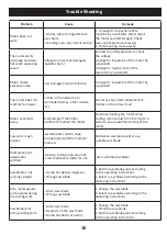
Page 17: ...ts easily Overloading of the motor insufficient coolinof the motor Avoid overloading the motor while cutting remove dust from the motor in order to ensure optimal cooling of the motor Saw cut is rough orwavy Saw blade dull tooth shape not appropriate forthe material thickness Resharpen saw blade and or use suitable saw blade Workpiece pulls awayand or splinters Excessive cutting pressure and or sa...

Page 18: ...17 ...

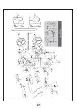
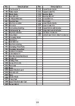
Page 19: ...od 17 Rubber Tyre 55 Bolt M6 16 18 Upper Pulley Shaft 56 Flat Washer 6 19 Circlip for Shaft 8 57 Big Flat Washer 8 20 Horizontal Shaft 58 Nut M8 21 Upper Wheel Shaft Seat 59 Setting Knob for Blade Tracking Adjustment 22 Thin Nut M10 60 Setting Knob for Blade Guard 23 U Shaped Bracket 61 Pressing Spring 24 Central Spindle 62 Wing Cap 25 Wing Spring 63 Locking Knob 26 Guide Plate Assembly 64 Bolt M6...

Page 20: ...118 Upper Microswitch Cable 86 Flat Washer 10 119 Lower Microswitch Cable 87 Rip Fence Holder 120 End Wire Connector 88 Stop Block 121 Cable Gland Strain Relief Connector 89 Clamping Block 90 Rip Fence 91 Bolt M6 10 92 Rip Fence Spring 93 Clamping Press Plate 94 Clamping Screw Rod 95 Suction Connector 96 Lock Washer 5 97 Machine Body Weldment 98 Circlip 14 99 Sliding Plate 100 Screw ST3 5 9 5 101 ...

Page 21: ...rew ST2 9x6 5 126 Lamp Cable 1 127 SM2 54 2P Connector Male End 128 SM2 54 2P Connector Female End 129 Lamp Cover 130 Lamp 131 Lamp Cable 2 132 Lamp Holder 133 Screw ST4 8x13 134 Lamp Base Bracket 135 Shade 136 Screw M4x16 137 Lamp Cable 3 138 Lamp ON OFF Switch 139 Cable Holder U 3 3 140 Double Core Cable 141 Single Core Cable 1 142 Single Core Cable 2 ONLY FOR DJMBAS80 ...

Page 22: ...Date 05 17 2021 EN ISO 12100 2010 EN 55014 1 2017 EN 55014 2 2015 EN 61000 3 2 2014 EN 61000 3 3 2013 Band Saw Part No DJMBAS80 2006 42 EC Machinery Directive 2014 30 EU EMC Directive 21 ...

Page 23: ...12 22 ...

Reviews: