KX-2 Robot
–
User’s Manual
Peak Robotics, Inc.
4747 Centennial Blvd; Colorado Springs, CO 80919
Ph 719.598.3555,
Printed: 3/3/2021
Page
12
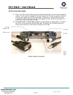
6.6 User Inputs/Outputs: There are three digital inputs, two analog inputs, and three digital outputs
available at base of the robot. These are described in more detail later in this document.
6.7 Internal Motor Drives: All joints and gripper are servo-driven with drives mounted inside the robot
next to each motor. A USB/CANOpen adapter is mounted inside the robot and provides a USB
interface between the robot and PC.
6.8 Barcode Reader: A 1D barcode reader is integrated into the gripper.
6.9 User-Supplied PC: A standard PC with Windows 7 or newer is required to control the robot. The
robot connects to the PC via a USB 2.0 port. An RS232 serial port is required for the barcode
reader (a serial/USB adapter is provided with the robot).
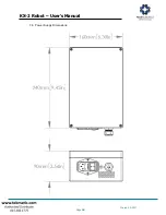
6.10 Power: The robot uses 57 VDC for motor power, and 24VDC for logic power. The two DC power
supplies are mounted inside the power supply box.
Power Supply Box
6.11 Universal DLL: A universal .NET 4.0 DLL (provided with robot) is to be used by the top-level
sequencing program, which typically is written in VB, C++, C#, etc.
6.12 Scheduling Software: As an option, PAA Overlord can be used for synchronizing the robot with
6.13 Gripper: The robot comes standard with an electric gripper. There are no air lines inside the
robot, so a pneumatic gripper is not an option.
6.14 Serial Number Tag: A serial number tag is located on the rear of the shoulder housing. A
second serial number tag is located on the side of the power supply box.
Summary of Contents for PEAKROBOTICS KX-2
Page 2: ......


