background image

19

W

R

G

C

Y

W

R

G

Y

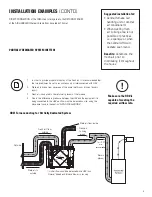
Standard Furnace Interlock Wiring

THERMOSTAT

TERMINALS

FURNACE

24-VOLT

TERMINAL BLOCK

FOUR
WIRE

TWO WIRE

heating only

TWO

WIRE

COOLING SYSTEM

W

R

G

C

Y

W

R

G

Y

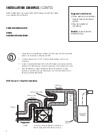
Alternate Furnace Interlock Wiring

THERMOSTAT

TERMINALS

FURNACE

24-VOLT

TERMINAL BLOCK

FOUR
WIRE

TWO WIRE

heating only

TWO

WIRE

COOLING SYSTEM

WIRE JOINT

WIRING DIAGRAM


(CONT'D)

WIRING DIAGRAM TO 
FURNACE

FOR A FURNACE 

CONNECTION TO
A COOLING SYSTEM:

On some newer furnaces and older 
thermostats, energizing the R and 
G terminal at the furnace has the 
effect of energizing the Y at the 
thermostat and thereby turning on 
the cooling system. If you identify this 
type of thermostat, you must use the 
“Alternate Furnace Interlock Wiring”

Standard Accessory Control Contact

Alternative Accessory Control Contact

As per building codes and installation requirements for combustion appliances: 

Air return ducts, or openings for air return, should not be placed in enclosed spaces containing combustion 

appliances that are subject to spillage.

Summary of Contents for PHRVR100 ES

Page 1: ...er operating at a higher static pressure After installation the compatibility of the two pieces of equipment must be confirmed by measuring the airflow of the Heat Recovery Ventilator using the balancing procedure found in this manual It is always important to assess how the operation of any HRV may interact with vented com bustion equipment i e Gas Furnaces Oil Furnaces Wood Stoves etc NEVER inst...

Page 2: ... Installing the ducting to the weatherhood 11 INTERIOR DUCTING INSTALLATION General Tips 12 Installing duct to HRV 12 Supply Exhaust Air Grilles Location 12 HRV INSTALLATION 13 AIRFLOW ADJUSTMENT BALANCING General preparation 15 Adjusting airflow using integrated balancing system 15 Balancing steps 18 LOW VOLTAGE CONTROL SYSTEMS 17 WIRING DIAGRAM 18 TROUBLESHOOTING 20 HRV MAINTENANCE CHART 21 Note...

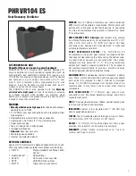
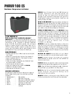
Page 3: ... RECOVERY CORE Aluminum heat recovery core covered by a limited lifetime warranty Core dimensions are 8 5 x 8 5 216 x 216 mm with a 12 305 mm depth Our heat exchangers are designed and manufactured to withstand extreme temperature variations FROST PREVENTION SYSTEM The PHRVR100 ES incorporates a unique and quiet internal recirculation defrost that does not depressurize the home during the defrost ...

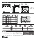
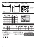
Page 4: ...uency Amps 120V 60Hz 1 4A 3 plug in power cord w 3 prong plug Pa in wg L s cfm L s cfm L s cfm 25 0 1 61 129 62 131 62 131 50 0 2 57 121 58 123 58 123 75 0 3 53 112 54 114 54 114 100 0 4 49 104 50 106 50 106 125 0 5 45 95 46 97 46 97 150 0 6 42 89 42 89 42 89 175 0 7 38 81 38 81 38 81 200 0 8 33 70 34 72 33 70 225 0 9 28 59 29 61 28 59 250 1 0 23 49 23 49 23 49 EXT STATIC PRESSURE NET SUPPLY AIR F...

Page 5: ...es Motors come with permanently lubricated sealed ball bearings to guarantee long life and maintenance free operation Covered by a seven 7 year warranty HEAT RECOVERY CORE Aluminum heat recovery core covered by a limited lifetime warranty Core dimensions are 8 5 x 8 5 216 x 216 mm with a 12 305 mm depth Our heat exchangers are designed and manufactured to withstand extreme temperature variations F...

Page 6: ...20V 60Hz 1 4A 3 plug in power cord w 3 prong plug Pa in wg L s cfm L s cfm L s cfm 25 0 1 61 129 62 131 62 131 50 0 2 57 121 58 123 58 123 75 0 3 53 112 54 114 54 114 100 0 4 49 104 50 106 50 106 125 0 5 45 95 46 97 46 97 150 0 6 42 89 42 89 42 89 175 0 7 38 81 38 81 38 81 200 0 8 33 70 34 72 33 70 225 0 9 28 59 29 61 28 59 250 1 0 23 49 23 49 23 49 EXT STATIC PRESSURE NET SUPPLY AIR FLOW GROSS AI...

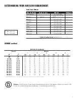
Page 7: ... 53 25 60 28 501 1000 47 93 45 21 53 24 60 28 68 31 75 35 1001 1500 94 139 60 28 68 31 75 35 83 38 90 42 1501 2000 140 186 75 35 83 38 90 42 98 45 105 49 2001 2500 187 232 90 42 98 45 105 49 113 52 120 56 2501 3000 233 279 105 49 113 52 120 56 128 59 135 63 3001 3500 280 325 120 56 128 59 135 63 143 66 150 70 3501 4000 326 372 135 63 143 66 150 70 158 73 165 77 4001 4500 373 418 150 70 158 73 165 ...

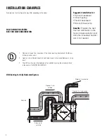
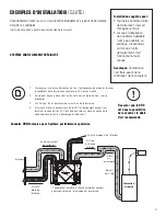
Page 8: ...reas of the home requiring local exhaust bathroom kitchen laundry room 2 Fresh air is distributed directly to habitable rooms in the house bedrooms living room 3 The HRV s airflow must be balanced after installation using the procedure found in the section AIRFLOW BALANCING Suggested installation for Hydronic baseboard Infloor heating Electric baseboard Mini split heat pump Benefits Provides the b...

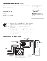
Page 9: ...proper distribution of the fresh air it is recommended that the furnace blower be set to run continuously or interconnected with HRV 2 Stale air is drawn from key areas of the home bathroom kitchen laundry room 3 Fresh air is supplied to the return air plenum of the furnace 4 Due to the difference in pressure between the HRV and the equipment it is being connected to the HRV s airflow must be bala...

Page 10: ... operate when ventilation from HRV is required The furnace should be set to run continuously or interlocked with HRV 2 A minimum separation of 1m 39 is recommended between the two direct connections 3 In order to prevent exhausting any fresh air the HRV s exhaust air connection should be upstream of the HRV s supply air connection when ducting to the furnace s cold air return 4 Due to the differen...

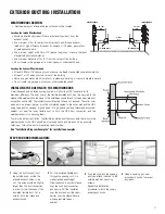
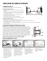
Page 11: ...uter liner which acts as a vapor barrier must be completely sealed to the outer wall and the HRV using tape and or caulking A good bead of high quality caulking preferably acoustical sealant will seal the inner flexible duct to both the HRV duct connection and the weatherhood prior to securing them To minimize airflow restriction the flexible insulated duct that connects the two outside weatherhoo...

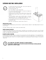
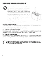
Page 12: ...ible duct to prevent leakage between the ducting and the duct connection In the case of solid ducting slide duct over duct connection screw in place and seal SUPPLY AIR GRILLES LOCATION In homes without a forced air furnace fresh air should be supplied to all habitable rooms including bedrooms and living areas It should be supplied from high wall or ceiling locations Grilles that diffuse the air c...

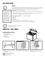
Page 13: ...tem Bathroom exhaust fans unless they are specifically designed for this purpose These appliances may cause lint dust or grease to collect in the HRV damaging the unit Connecting any of these types of appliances to the HRV will void your warranty Have a nearby power supply 120 volts 60Hz Choose a location which allows the possibility of mounting the unit to supporting beams The unit should be leve...

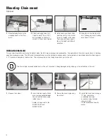
Page 14: ...ion This water should flow into a nearby drain or be taken away by a condensate pump The HRV and all condensate lines must be installed in a space where the temperature is maintained above the freezing point A P trap should be made in the drain line This will prevent odors from being drawn back up into the unit 2 Invert the drain nipple Make sure to place gasket between the unit and the drain nipp...

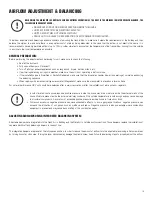
Page 15: ...operating at normal speed during the balancing sequence When reading with a mechanical type manometer Magnehelic make sure the manometer is placed on a level surface For optimal performance HRV unit should be re balanced after a major renovation or after the installation of extra grilles or registers In cold climates continuous excessive positive pressure inside the house may drive moisture inside...

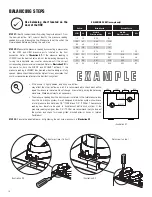
Page 16: ...e airflow may affect the other airflow as well It is recommended to check each airflow again to make sure the value did not change dramatically during the balancing procedure Make adjustments as necessary The pressure reading from the duct connection refers to the total pressure loss from the distribution system A well designed distribution system should have a total pressure loss between 0 4 100P...

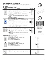
Page 17: ...ntilation mode for day and night conditions No battery to replace all programmed settings are retained during power outage Maintenance reminder indicator Error code messages reduce troubleshooting time DIR DG MODE button provides 3 modes of operations Ventilation Recircula tion and Standby User selected fan speed Reduced Medium Normal and 20 minutes per hour AUTO setting allows the homeowner to de...

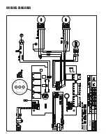
Page 18: ...18 WIRING DIAGRAM LOW SPEEDS 90V 75V J4 J5 J6 ...

Page 19: ...ECTION TO A COOLING SYSTEM On some newer furnaces and older thermostats energizing the R and G terminal at the furnace has the effect of energizing the Y at the thermostat and thereby turning on the cooling system If you identify this type of thermostat you must use the Alternate Furnace Interlock Wiring Standard Accessory Control Contact Alternative Accessory Control Contact As per building codes...

Page 20: ... power supply at site Have electrician check supply voltage Ductwork is restricting airflow Check duct installation Improper speed control setting Increase the speed of the HRV i e change unit control from REDUCED to NORMAL speed HRV airflow improperly balanced Have contractor balance HRV airflows Ducting has fallen down or been disconnected from HRV Have contractor reconnect ducting Supply air fe...

Page 21: ...ntial damages incurred in the use of the ventilation system Powrmatic is not responsible for providing an authorized service centre near the purchaser or in the general area Powrmatic reserves the right to supply refurbished parts as replacements Transportation removal and installation fees are the responsibility of the purchaser The purchaser is responsible to adhering to all codes in effect in h...

Page 22: ... 418 683 2708 F 418 683 8860 quebec powrmatic ca Toronto 111 Staffern Drive Concord ON L4K 2R2 T 905 660 0033 F 905 660 8881 toronto powrmatic ca Halifax 100 Wright Ave Dartmouth NS B3B 1L2 T 902 454 8684 F 902 453 5875 halifax powrmatic ca Ottawa 1412 Star Top Rd Goucester ON K1B 4V7 T 613 230 7160 F 613 230 0685 ottawa powrmatic ca London 1064 Hargrieve Road London ON N6E 1P5 T 519 675 1491 F 51...

Page 23: ...tatique est plus élevée Une fois l installation terminée la compatibilité des deux appareils doit être confirmée en mesurant le débit d air du ventilateur récupérateur de chaleur au moyen de la procédure d équilibrage du présent manuel Il importe de toujours évaluer l interaction du VRC avec les appareils de chauffage à évacuation fournaise à gaz fournaise à mazout poêle à bois etc AVERTISSEMENT N...

Page 24: ... 32 INSTALLATION DES CONDUITS EXTÉRIEURS Emplacement des hottes 33 Installation de l ensemble des conduits avec hottes 33 INSTALLATION DES CONDUITS INTÉRIEURS Conseils pratiques 34 Installation des conduits sur le VRC 34 Emplacement des grilles d approvisionnement et d évacuation 34 INSTALLATION DU VRC 35 ÉQUILIBRAGE DU DÉBIT D AIR Préparation générale 37 Ajustement des débits d air 37 Étapes de b...

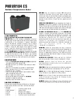
Page 25: ... RÉCUPÉRATION Noyau récupérateur de chaleur en aluminium couvert par une garantie à vie limitée Dimensions de 8 5 po x 8 5 po 216 x 216 mm avec une profondeur de 12 po 305 mm Nos échangeurs de chaleur sont conçus et fabriqués pour résister à des variations extrêmes de température SYSTÈME DE PRÉVENTION DE GEL Le VRC PHRVR100 ES intègre un système de dégivrage unique avec recirculation interne qui n...

Page 26: ...rais Distribution d air frais 22 4 po 569 mm 21 5 po 546 mm 14 5 po 368 mm 15 po 381 mm 17 9 po 455 mm 15 5 8 po 397 mm Pa po d eau L s pcm L s pcm L s pcm 25 0 1 61 129 62 131 62 131 50 0 2 57 121 58 123 58 123 75 0 3 53 112 54 114 54 114 100 0 4 49 104 50 106 50 106 125 0 5 45 95 46 97 46 97 150 0 6 42 89 42 89 42 89 175 0 7 38 81 38 81 38 81 200 0 8 33 70 34 72 33 70 225 0 9 28 59 29 61 28 59 2...

Page 27: ...on permanente avec roulements à billes scellés pour garantir un fonctionnement durable et sans entretien Couvert par une garantie de sept 7 années NOYEAU DE RÉCUPÉRATION Noyau récupérateur de chaleur en aluminium couvert par une garantie à vie limitée Dimensions de 8 5 po x 8 5 po 216 x 216 mm avec une profondeur de 12 po 305 mm Nos échangeurs de chaleur sont conçus et fabriqués pour résister à de...

Page 28: ...112 54 114 54 114 100 0 4 49 104 50 106 50 106 125 0 5 45 95 46 97 46 97 150 0 6 42 89 42 89 42 89 175 0 7 38 81 38 81 38 81 200 0 8 33 70 34 72 33 70 225 0 9 28 59 29 61 28 59 250 1 0 23 49 23 49 23 49 PRESSION STATIQUE EXTERNE DÉBIT NET D AIR FRAIS DÉBIT BRUT D AIR FRAIS VICIÉ C F L s cfm Chauffage 0 32 30 64 50 65 69 0 02 0 32 38 81 65 63 68 0 01 0 32 48 102 100 60 66 0 00 25 13 31 66 65 62 65 ...

Page 29: ...min L s Pi3 min L s 500 47 30 128 38 18 45 21 53 25 60 28 501 1000 47 93 45 21 53 24 60 28 68 31 75 35 1001 1500 94 139 60 28 68 31 75 35 83 38 90 42 1501 2000 140 186 75 35 83 38 90 42 98 45 105 49 2001 2500 187 232 90 42 98 45 105 49 113 52 120 56 2501 3000 233 279 105 49 113 52 120 56 128 59 135 63 3001 3500 280 325 120 56 128 59 135 63 143 66 150 70 3501 4000 326 372 135 63 143 66 150 70 158 7...

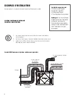
Page 30: ...est aspiré à partir des endroits clés de la maison salle de bains cuisine buanderie 2 L air frais est distribué parmi les pièces habitables chambres à coucher salon 3 Le débit d air du VRC doit être confirmé sur place au moyen de la procédure d équilibrage du présent manuel d installation Installation suggérée pour Plinthe à eau chaude Plancher chauffant Plinthe électriques Thermopompe mural biblo...

Page 31: ... est nécessaire de faire fonctionner le ventilateur de la fournaise pendant que le VRC est en marche 2 Air vicié est aspiré à des endroits clés de la maison salle de bain cuisine buanderie 3 L air frais est fourni au plénum de retour d air de la fournaise 4 En raison de l écart de pression entre le VRC et l équipement auquel il est raccordé le débit d air du VRC doit être équilibré sur place au mo...

Page 32: ...de la fournaise doit fonctionner continuellement ou bien le fonctionnement du VRC doit être synchronisé avec le ventilateur de la fournaise 2 Une séparation minimum de 1m 36 po est recommandée entre les deux connexions directes 3 Afin d éviter l évacuation d air frais la connexion d évacuation du VRC devrait être située en amont de la connexion d approvisionnement du VRC lorsqu on les branche à la...

Page 33: ... complètement scellé sur le mur extérieur et le VRC à l aide de ruban ou de produit de calfeutrage Déposez un cordon de produit de calfeutrage de première qualité du mastic d isolation acoustique de préférence pour sceller le conduit flexible intérieur à l orifice du VRC et à la hotte de protection avant de procéder à l encastrement Pour réduire au minimum la restriction de débit d air le conduit ...

Page 34: ...hets Ensuite installez un attache câble par dessus le conduit flexible afin de prévenir des fuites entre le conduit et le collet Dans le cas d un conduit galvanisé faites le glisser sur le collet vissez en place et scellez le EMPLACEMENT DES GRILLES D APPROVISIONNEMENT Dans les maisons non munies d une fournaise à air pulsé il faut distribuer de l air frais dans toutes les pièces d habitation y co...

Page 35: ... aspirateur central Ces électroménagers peuvent entraîner l accumulation de charpie de poussière ou de graisse dans le VRC et l endommager Assurez vous d avoir une source d alimentation près 120 volts 60Hz Choisissez un emplacement où il y a possibilité de montage à des poutres de support L unité doit être au niveau afin d assurer un drainage approprié Afin de minimiser le bruit ne pas installer l...

Page 36: ... d écouler vers le drain avoisinant ou être aspirée par une pompe à condensat Le VRC et toutes les canalisations de condensats doivent être installés dans un endroit où la température ambiante est maintenue au dessus du point de congélation Faires un siphon en P dans un tuyau d écoulement Ce siphon empêche le retour des odeurs vers l appareil 2 Inverser le raccord de vidange Assurez vous de placer...

Page 37: ...omètre analogique Magnehelic assurez vous que le manomètre est placé sur une surface plane Afin d assurer une performance optimal le VRC devrait être rééquilibré après toute rénovation majeure ou après l ajout de nouveaux conduits Dans les endroits froids la continuelle pression positive excessive à l intérieur de la maison peut chasser l humidité à l intérieur des murs extérieurs de la maison L h...

Page 38: ...llée le réglage d un débit d air peut affecter le débit d autres aussi Il est donc recommandé de vérifier chaque débit d air à nouveau pour s assurer que la valeur n a pas changer considérablement Faites les ajustements nécessaires La lecture de pression de la connexion du conduit se réfère à la perte totale du système de distribution Un système de distribution bien conçu doit avoir une perte de p...

Page 39: ...glable et le mode de ventilation pour les conditions de jour et de nuit Indicateur rappel d entretient Messages d erreur de code réduit le temps de dépannage DIR DG Le bouton MODE fournit trois mode de fonctionnement Ventilation Recirculation et en attente Sélection de la vitesse du ventilateur par l utilisateur Vitesse Réduite vitesse moyenne vitesse normal et 20 min h Réglage AUTO permet au prop...

Page 40: ...40 SCHÉMAS ÉLECTRONIQUES PHRVR100 ES LOW SPEEDS 90V 75V J4 J5 J6 ...

Page 41: ...itation de la borne Y du thermostat et conséquemment la mise sous tension du système de refroidissement Si votre système est muni d un tel type de thermostat vous devez respecter le câblage de verrouillage de la fournaise secondaire Câblage standard de synchronisation avec une fournaise Contact de commande des accessoires secondaires Ne raccordez jamais un courant alternatif de 120V aux bornes de ...

Page 42: ... efficacité du VRC Vérifiez le réseau de conduits Mauvais réglage de la commande de vitesse Augmentez la vitesse du VRC i e changez la vitesse de l appareil de vitesse RÉDUITE à vitesse NORMALE avec le contrôle Déséquilibre du débit d air du VRC Demandez au contracteur d équilibrer le VRC Les conduits ont tombé ou ne sont plus branchés au VRC Demandez au contracteur de replacer les conduits L air ...

Page 43: ...enu de respecter tous les codes en vigueur dans sa région Les pièces y compris les pièces de rechange posées ultérieurement sont garanties pendant 5 ans à partir de la date d achat de l appareil Les moteurs des ventilateurs sont garantis pendant 7 ans à partir de la date d achat S il n existe aucune preuve d achat la date associée au numéro de série devient la date du début de la période de garant...

Page 44: ...8 F 418 683 8860 quebec powrmatic ca Toronto 111 Staffern Drive Concord ON L4K 2R2 T 905 660 0033 F 905 660 8881 toronto powrmatic ca Halifax 100 Wright Ave Dartmouth NS B3B 1L2 T 902 454 8684 F 902 453 5875 halifax powrmatic ca Ottawa 1412 Star Top Rd Goucester ON K1B 4V7 T 613 230 7160 F 613 230 0685 ottawa powrmatic ca London 1064 Hargrieve Road London ON N6E 1P5 T 519 675 1491 F 519 675 4725 l...

Reviews: