


UltiMate
®
3000 Viper™ Capillary Kits for Intelligent LC (LCi) System Solutions
Quick Installation Guides
January 2010
Rev. 02
Page 23
©
2010 Dionex
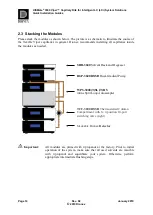
4.4 Flow Schematic
The figure below shows the schematic setup of the on-line SPE configuration.
Install your Viper capillaries according to the information of Table 8 and the system stack
schematic (
4.3).
Figure 14:
Flow schematic of the on-line SPE setup
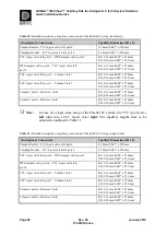
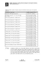
Table 8:
Detailed description of capillary connections of the on-line SPE setup
Description of Connections
Capillary Dimensions (ID x L)
PumpLeft outlet – TCC 6-port valve right, port 5
0.18 mm/0.007” x 950 mm
PumpRight outlet – WPS sampler valve, port 5
0.18 mm/0.007” x 450 mm
TCC 6-port valve right, port 3 – SPE column inlet
RS: 0.13 mm/0.005” x 250 mm
SD: 0.18 mm/0.007” x 250 mm
TCC 6-port valve right, port 4 – Column inlet
RS: 0.13 mm/0.005” x 250 mm
SD: 0.18 mm/0.007” x 250 mm
WPS sampler valve, port 4 – TCC 6-port valve right,
port 2
RS: 0.13 mm/0.005” x 350 mm
SD: 0.18 mm/0.007” x 350 mm
SPE column outlet – TCC 6-port valve left, port 6
RS: 0.13 mm/0.005” x 350 mm
SD: 0.18 mm/0.007” x 350 mm
Column outlet – Detector inlet
RS: 0.13 mm/0.005” x 350 mm
SD: 0.18 mm/0.007” x 350 mm
Summary of Contents for UltiMate 3000 LCi
Page 2: ......


