waste lines, tubing from an autosampler to the Rheodyne
injection valve port, and tubing from the separator column to
the SRS.
The system plumbing depends primarily on the detection
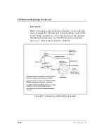
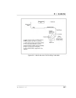
mode. Consult the proper fluid schematic in Section B.2.5.
The LC20 is plumbed with Dionex 10-32 ferrule fittings. If
you need instructions on how to install ferrule fittings, refer
to Installation of Dionex Ferrule Fittings (Document
No. 034213), provided in the LC20 Ship Kit.
Injection Valve Connections
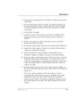
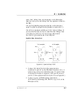
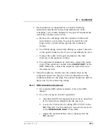
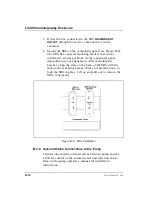
1. Connect the eluent line from the pump pressure
transducer to port #2 on the Rheodyne injection valve. A
label on top of the valve identifies ports #1 and #2. Ports
#3 through #6 follow in sequence, with port #6 close to
port #1 on the opposite side from port #2 (see Figure B-).
2. Connect a piece of PEEK tubing with ferrule
(P/N 043276) and fitting (P/N 043275) to port #3 on the
Rheodyne valve.
Figure B-3. Injection Valve Ports
B
•
Installation
Doc. 034859-02 9/93
B-7
Summary of Contents for LC20
Page 6: ...Contents iv Doc 034859 02 9 93 ...
Page 8: ...LC20 Chromatography Enclosure 1 2 Doc 034859 02 9 93 ...
Page 12: ...LC20 Chromatography Enclosure 2 2 Doc 034859 02 9 93 ...
Page 24: ...LC20 Chromatography Enclosure 2 14 Doc 034859 02 9 93 ...
Page 26: ...LC20 Chromatography Enclosure 3 2 Doc 034859 02 9 93 ...
Page 29: ...Figure 3 7 Drawing Sample 3 Operation and Maintenance Doc 034859 02 9 93 3 5 ...
Page 32: ...LC20 Chromatography Enclosure 3 8 Doc 034859 02 9 93 ...
Page 34: ...LC20 Chromatography Enclosure 4 2 Doc 034859 02 9 93 ...
Page 40: ...LC20 Chromatography Enclosure 4 8 Doc 034859 02 9 93 ...
Page 42: ...LC20 Chromatography Enclosure 5 2 Doc 034859 02 9 93 ...
Page 50: ...LC20 Chromatography Enclosure 5 10 Doc 034859 02 9 93 ...
Page 52: ...LC20 Chromatography Enclosure A 2 Doc 034859 02 9 93 ...
Page 56: ...LC20 Chromatography Enclosure B 2 Doc 034859 02 9 93 ...
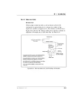
Page 65: ...Figure B 6 Electrochemical Cell Plumbing Schematic B Installation Doc 034859 02 9 93 B 11 ...

