DINSEO DIX TIG GO 1906.M HF Operation Manual Download Page 24

24

  Editing the maximum and minimum 

limits for welding parameters

Welding power source in STANDARD (Std) configuration: 
During TIG welding with HF ignition, the units allow you to modify  
the MINIMUM and MAXIMUM LIMITS for some WELDING  
PARAMETERS, thereby providing a more skilled welder and a 
more versatile welding power source.
Proceed as follows:
1)  Switch on the welding power source holding down the WELD-

ING PARAMETERS SELECTION key (T7).

2)  Press the WELDING PARAMETERS SELECTION Key (T7) 

a number of times to set the limits for the following welding  
parameters:

L10

L16

L15

L12

L11

T7

 L11 

  PRE-GAS duration (maximum limit settable from 1,00 

to 2,50 sec)

 L12 

 SLOPE UP duration (maximum limit settable from 5,00 

to 10,0 sec)

 L10 

 MINIMUM CURRENT for remote controls - minimum 

limit settable:

1906.M HF

2506.M HF

5 ÷ 220 A

5 ÷ 300 A

WARNING: If the minimum limit setting (for the remote control 
MINIMUM CURRENT) is greater than or equal to the value for the 
PRINCIPAL welding CURRENT 
 I

, you will weld at the PRINCI-

PAL welding CURRENT  I

, irrespective of the setting you have 

chosen for the remote control.

 L15 

 SLOPE DOWN duration (maximum limit settable from 

8,00 to 15,0 sec)

 L16 

 POST-GAS duration (maximum limit settable from 10,0 

to 25,0 sec)

To exit the setting phase, hold the WELDING PARAMETERS  
SELECTION key (T7) down for about 

1 second

. The values set 

are now active and welding can begin.

  Creating and memorising automatic 

welding points

Once you have defined the parameters the operator requires to do 
their work properly, you can save them in the memory and create 
a WELDING PROGRAM by proceeding as follows.

WARNING: To access the setting saving phase, the PRINCIPAL 
CURRENT LED 
 I

 must be switched on without flashing.

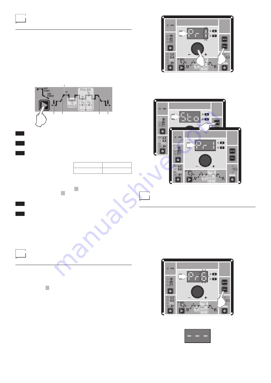
1)  Hold the “PRG” PROGRAM Key (T2) down for at least 

5

 con-

secutive seconds until the DISPLAY (D) reads 

Pr

, accom- 

panied by a flashing number (e.g. Pr 1).


In order to be able to choose WELDING PROGRAM that is 
free, simply rotate the ENCODER knob (E) and look for a  
program for which the control panel has all the LEDs for the 
various settings switched off.


It is also possible to overwrite a program already saved.

PULSE

SYN
FAST
SLOW

T2

D

E

2)  To SAVE the PROGRAM hold the “MEM” SAVE Key (T1) down 

until the DISPLAY reads 

“Sto”

.

3)  The WELDING PROGRAM has now been saved and its num-

ber appears in the DISPLAY (D) along with the other settings 
saved (corresponding LEDs on without flashing).

PULSE

SYN
FAST
SLOW

PULSE

SYN
FAST
SLOW

D

T1

D

  PROGRAMMED and/or  

MANUAL welding

PROGRAMMED WELDING

When the WELDING PROGRAM has been saved, the operator 
can weld using only pre-set values as they cannot edit any type 
of parameter/function. To edit, switch to MANUAL welding mode.

MANUAL WELDING

To go back to set/edit the parameters selected or to create a new 
program, proceed as follows:
1)  Hold the “PRG” PROGRAM Key (T2) down (about 

3

 sec-

onds) until the DISPLAY (D) shows the number of the program  
selected flashing (e.g. 

Pr6

).

PULSE

SYN
FAST
SLOW

T2

D

2)  Turn the ENCODER Key (E) anticlockwise until the DISPLAY 

(D) shows 3 dashes.

3)  Press and release the “PRG” PROGRAM key (T2) and the 

welding power source goes back to the initial operation con-
dition.

Summary of Contents for DIX TIG GO 1906.M HF

Page 1: ...G Welding Power Source S C H W E I S S E N W E L D I N G W E L D I N G S C H W E I S S E N S C H W E I S S E N Keep in secure area for future reference Operations manual DIX TIG GO 1906 M HF DIX TIG GO 2506 M HF ...

Page 2: ...n using particularly difficult cellulosic and basic electrodes Features The characteristics found in all welding power sources are Innovative and compact design Compact size and light weight for easy transportation Metallic main structure with shock proof plastic front panel Protective visor on the control panel Robust handle integrated into the chassis Digital control regulation and monitoring of...

Page 3: ...e 10 minutes The work cycle is considered to be X of this period of time If the permitted work cycle time is exceeded an overheat cut off occurs to protect the components around the welder from dangerous overheating Activation of thermal protection is signaled by t C flashing on control panel display for further information see the control panel manual After several minutes the overheat cut off re...

Page 4: ...ect to heightened electrical shock Connection to the electrical supply Connection of the welding power source to the user line electrical current must be performed by qualified personnel Before connecting the welding power source to the mains power supply make sure that rated voltage and frequency correspond to those provided by the mains power supply and that the welding power source s power swit...

Page 5: ...5 FIG A ...

Page 6: ...using an arc ignited by a tungsten electrode The molten bath and the electrode are protected by and inert gas for exam ple Argon This type of welding is used to weld thin sheet metal or when elevated quality is required 1 Connecting the welding cables Fig C Connect the gas hose to the Argon cylinder With the welding power source switched off Connect the ground cable to the snap on connector marked...

Page 7: ...les to the output terminals Positive and Negative of the welding power source attaching them to the clamp and ground with the polarity specified for the type of electrode being used Fig F Always follow the elec trode manufacturer s instructions The welding cables must be as short as possible they must be near to one another posi tioned at or near floor level Do not touch the electrode clamp and th...

Page 8: ...tive parameter With this kind of torch it is also possible to scroll the saved programmes by pressing the two and buttons Turn the knob to scroll the programmes until an empty and unused programme is found NOTE The value shown on the display during welding represents the effective current output with all types of control The digital control unit of the welding power source is fitted with a control...

Page 9: ...ents with increased risk of electroshock Product suitable for free circulation in the Euro pean Community Danger High voltage Grounding Positive pole snap in connector Negative pole snap in connector Connector for the remote control Warning Fast coupling TIG torch gas tube Before using the equipment you should carefully read the instructions included in this manual MMA welding TIG welding Special ...

Page 10: ...10 Wiring diagram DIX TIG GO 1906 M HF ...

Page 11: ...11 2101WA31 ...

Page 12: ...12 Wiring diagram DIX TIG GO 2506 M HF ...

Page 13: ...13 2101WB24 ...

Page 14: ... circuit 20 Full Bridge IGBT 21 Primary upper IGBT 22 Lower prima ry IGBT 23 Fan motor 24 Primary transformer start 25 Primary trans former end 26 Secondary rectifier 27 Rectifier diode ultrafast 28 R C Secundary diode varistor 29 Membrane keyboard 30 Primary rectifier 31 Interface for automation optional extra 32 Booster board 33 Digital interface PCB 34 Inverter PCB 35 Automation interface isola...

Page 15: ... by the LED that stays lit in the following order L1 TIG with HF ignition L2 TIG with Lift type ignition L3 ELECTRODE MMA L1 L2 L3 Calling up saved programs 25 Viewing the parameters set 25 Activating the VRD device 25 Auxiliary functions 25 Factory default 26 Error and protection conditions 26 Control panel 15 Introduction 15 Displaying the software version installed 17 Electrode welding MMA 17 T...

Page 16: ...s at the end of which the arc switches off automatically The tack welding function is divided into 3 types TIG LIFT DC tack welding TIG HF DC tack welding with a single DIX ARC COOL SPOT point TIG HF DC tack welding with a Multi DIX ARC COOL SPOT function See the relevant paragraphs in the subsequent pages of this manual DISPLAY Displays the selections made using the various Keys with corre spondi...

Page 17: ...NITIAL welding CURRENT WARNING Only programmable for the welding process TIG with HF ignition and 2 TIME welding mode active L21 FINAL welding CURRENT WARNING Only programmable for the welding process TIG with HF ignition and 2 TIME welding mode active WARNING This special parameter is only to be activated by qualified personnel or those trained by technicians Displaying the software version insta...

Page 18: ...rrent is created by pushing the torch button only after having touched the workpiece with the electrode 3 Press the WELDING MODE SELECTION Key T6 and go to one of the 4 options available L4 2T L5 4T L6 SWITCH L7 SPOT WELD T7 L1 L2 4 Turn the ENCODER Knob E until the DISPLAY D shows the CURRENT VALUE at which you wish to weld 5 By pushing the WELDING PARAMETERS SELECTION T7 key a number of times it...

Page 19: ...actually welding T5 Multi spot welding with Multi DIX ARC COOL SPOT function with TIG HF DC welding The Multi DIX ARC COOL SPOT function can be used for cold tacking in quick succession to further extend the benefits of an individual DIX ARC COOL SPOT point Thanks to the Perfect Point mode DIX ARC COOL SPOT guarantees perfect centring of the welding point The Perfect Point mode is activated by tou...

Page 20: ...CIPAL welding CURRENT I1 1906 M HF 2506 M HF 5 220 A 5 300 A L15 SLOPE DOWN duration 0 0 8 0 sec L21 FINAL welding CURRENT 1906 M HF 2506 M HF 5 220 A 5 300 A WARNING This can only be programmed when 4 STROKES or SWITCH welding mode is activated L16 POST GAS duration 0 5 25 0 sec WARNING When the post gas LED flashes and the LED I1 is on at the same time this means that the welding power source is...

Page 21: ...PULSE key T3 until the requited pulsation is active Press the WELDING PARAMETERS SELECTION Key T7 a number of times to set the following in addition to the WELDING PARAMETERS defined as being BASIC PULSE SYN FAST SLOW T5 PULSE SYN FAST SLOW T3 L19 L20 L22 T7 L19 BASE CURRENT Ib 1906 M HF 2506 M HF 5 220 A 5 300 A L20 PEAK CURRENT Ip 1906 M HF 2506 M HF 5 220 A 5 300 A L22 PULSATION FREQUENCY f 190...

Page 22: ...ON key T7 down for about 1 second 3B FAST PULSE SWITCH Press the PULSE key T3 until the requited pulsation is active FAST LED on Press the WELDING MODE SELECTION key T6 until the SWITCH welding mode is active SWITCH LED on Press the WELDING PARAMETERS SELEC TION Key T7 a number of times to set the PULSE SYN FAST SLOW T3 T6 PULSE SYN FAST SLOW T3 T6 following in addition to the WELDING PARAMETERS d...

Page 23: ...ther modify the WELDING PARAMETERS thereby providing a more skilled welder and a more versatile welding power source Activation will only take place after the welding power source configuration is changed from STANDARD Std to SPECIAL SPE which must be done as follows 1 When the welding power source is off push and hold the PRG PROGRAM key down T2 2 Start the welding power source by turning the pow...

Page 24: ...meters the operator requires to do their work properly you can save them in the memory and create a WELDING PROGRAM by proceeding as follows WARNING To access the setting saving phase the PRINCIPAL CURRENT LED I1 must be switched on without flashing 1 Hold the PRG PROGRAM Key T2 down for at least 5 con secutive seconds until the DISPLAY D reads Pr accom panied by a flashing number e g Pr 1 In orde...

Page 25: ...lding power source 2 Position JUMPER W1 on the DIGITAL INTERFACE BOARD in the correct position following the instructions given in Figure A 3 Use a suitable screwdriver to tighten the 4 screws that fix the control panel to the welding power source 4 Start the welding power source by pushing the switch on the rear panel to position I FIG A 2000HB06 When the MTH control panel switches on the VRD LED...

Page 26: ...rt ment to resolve problems more easily as quickly as possible and thanks to the user s reports also because in the meantime the welding power source will not allow the operator to do their work Table 1 Display Diagnosis E01 PRESSURE SWITCH This message appears when the cooling equipment is connected to the welding power source and its pressure switch does not close due to a lack of pressure in th...

Reviews: