


DN3PS2 Original Betriebsanleitung Original instruction manual
DN3PS2
Stand: 29.09.2017
Seite 7 von 12
Date: 2017-09-29
Page 7 of 12
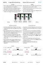
Schaltschwelle Einstellung
•
Gerät an die Betriebsspannung anschließen.
•
Die Taste SET ca. 3s betätigt halten, bis alle LED rot
blinken.
•
Nach der Betätigung blinken die LED rot entsprechend
der Binärkombination der aktuellen Parameterstufe
(Tabelle 2).
•
Mit jeder kurzen Betätigung der SET Taste wird die
nächsthöhere Stufe zugewiesen.
•
Durch Betätigen der SET Taste für ca. 2s wird der neue
Wert dauerhaft gespeichert und der Einstellmodus
verlassen.
Switching value adjusting
•
Connect the unit to the power supply.
•
Activate button SET for approximately 3s.
•
After the actuation the LED are flashing red according
to the binary combination of the actual parameters ad-
justment (table 2).
•
The value of the parameters increases one step after
every short actuation of the button SET.
•
To memorize the new value permanently and quit the
adjusting mode the button has to be actuated nearly
2s.
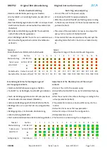
Tabelle 2:
Einstellbereich der Stillstand Schaltschwelle
Table 2:
Adjustment range of the standstill switching value
Tabelle 2
Position
1
2
3
4
5
6
7
8
9
10
11
12
13
14
15
Werteinstellung
LED: b8 / OK
Table 2 value
LED: b4 / STOP
adjustment
b2
b1
Kontakte aktiv Contacts on [mV] 50
55
60 65 70
75
80
200
230 250 300 350 400 460 500
Kontakte offen Contacts off [mV] 120 120 120 120 120 120 120 1000 1000 1000 1000 1000 1000 1000 1000
Einstellung der Einschaltverzögerungszeit
der Ausgangskontakte
•
Gerät an die Betriebsspannung anschließen.
•
Taste SET ca. 6s betätigen, bis alle LED grün blinken.
•
Nach der Betätigung blinken die LED entsprechend
dem aktuellen Parameterwert (Tabelle 3).
•
Jede kurze Betätigung erhöht den Wert eine Stufe.
•
Betätigen für ca. 2s speichert den neu eingestellten
Wert.
•
Betätigungstop ≥ 20s beenden die Einstellung.
•
Alte Einstellung bleibt aktiv.
•
Die Funktion bleibt während der Einstellung erhalten.
Adjustment of the ON-delay time of the output
contacts
•
Connect the unit to the power supply.
•
Activate the button SET for ca. 6s till all LED are flashing
green.
•
After the actuation the LED are flashing according to the
actual parameter (table 3).
•
The parameter increases one step after every short ac-
tuation.
•
Activation for 2s saves the new parameter.
•
Activation stop ≥ 20s ends the configuration.
•
Old parameter is active.
•
The function is active during the configuration.
Tabelle 3
Position
1
2
3
4
5
6
7
8
9
10
11
12
13
14
15
Werteinstellung
LED: b8 / OK
Table 3 value
LED: b4 / STOP
adjustment
b2
b1
Verzögerung [s]
time delay [s]
0,5
1
2
3
4
5
6
7
8
10
12
14
16
18
20


