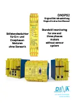
DN3PS2 Original Betriebsanleitung Original instruction manual
DN3PS2
Stand: 29.09.2017
Seite 4 von 12
Date: 2017-09-29
Page 4 of 12
Sicherheitsbestimmungen
•
Das Gerät darf nur von einer Elektrofachkraft oder unterwie-
senen Personen installiert und in Betrieb genommen werden,
die mit dieser Betriebsanleitung und den geltenden
Vorschriften über Arbeitssicherheit und Unfallverhütung
vertraut sind.
•
Beachten Sie die VDE- sowie die örtlichen Vorschriften,
insbesondere hinsichtlich der Schutzmaßnahmen.
•
Halten Sie beim Transport, der Lagerung und im Betrieb die
Bedingungen nach EN 60068-2-1, 2-2 und 2-6 ein.
•
Werden die Vorschriften nicht beachtet, kann Tod, schwere
Körperverletzung oder hoher Sachschaden die Folge sein.
•
Bei Not-Halt Anwendungen muss der automatische
Wiederanlauf der Maschine verhindert werden.
•
Durch eigenmächtige Umbauten erlischt jegliche
Gewährleistung. Es können dadurch Gefahren entstehen, die
zu schweren Verletzungen oder sogar zum Tod führen.
•
Montieren Sie das Gerät in einen Schaltschrank mit IP54
Schutz. Staub und Feuchtigkeit können sonst zu Beeinträch-
tigungen der Funktionen führen. Der Einbau in einem Schalt-
schrank ist zwingend.
•
Sorgen Sie an allen Ausgangskontakten bei kapazitiven und
induktiven Lasten für eine ausreichende Schutzbeschaltung.
•
Das Gerät ist unter Berücksichtigung der nach DIN EN
50274, VDE 0660-514 geforderten Abstände einzubauen.
•
Während des Betriebes stehen Schaltgeräte unter
gefährlicher Spannung. Schutzabdeckungen dürfen nicht
entfernt werden.
•
Wechseln Sie das Gerät nach dem ersten Fehlerfall aus.
Entsorgen Sie es sachgerecht nach Ablauf der Lebensdauer.
•
Bewahren Sie diese Produktinformation auf.
Safety regulations
•
The unit may only be installed and operated by those who
are qualified electrical engineers or have received sufficient
training and are familiar with both these instructions and the
current regulations for safety at work and accident
prevention.
•
Follow VDE, EN as well as local regulations especially as
regards preventative measures.
•
Transport, storage and operating conditions should all
conform to EN 60068-2-1, 2-2 and 2-6.
•
Ignoring the safety regulations can lead to death, serious
injury or cause considerable damage.
•
In emergency stop applications must be ensured that the
machine cannot start up again automatically!
•
Any warranty is void following unauthorised modifications.
This can lead to death, serious injury or cause considerable
damage.
•
The unit should be mounted in a cabinet with a protection
class of IP54. Otherwise dampness and dust could lead to
functional impairment. The installation in a control cabinet is
imperative.
•
Adequate fuse protection must be provided on all output
contacts especially with capacitive and inductive loads.
•
The unit must be installed following the specification of DIN
EN 50274, VDE 0660-514 regarding the required distances.
•
During operation, parts of the electronic switchgear carry
high voltage. Removing protective covers is not allowed.
•
The device must be replaced after the first malfunction and
properly disposed after reaches the end of its service life.
•
Keep the operating instructions.
Wichtiger Hinweis
•
Das beschriebene Produkt wurde entwickelt, um als Teil
eines Gesamtsystems sicherheitsrelevante Funktionen zu
übernehmen.
•
Das Gesamtsystem wird durch Sensoren, Auswerte- und
Meldeeinheiten sowie Konzepte für sichere Abschaltungen
gebildet.
•
Es liegt in der Verantwortung des Herstellers einer Anlage
oder Maschine die korrekte Gesamtfunktion sicherzustellen.
•
Der Hersteller der Anlage ist verpflichtet, die Wirksamkeit
des implementierten Sicherheitskonzepts innerhalb des
Gesamtsystems zu prüfen und zu dokumentieren.
•
Dieser Nachweis ist nach jeder Modifikation am Sicherheits-
konzept bzw. an den Sicherheitsparametern erneut zu
erbringen.
•
DINA Elektronik ist nicht in der Lage, die Eigenschaften
eines Gesamtsystems zu garantieren, das nicht von DINA
konzipiert wurde.
•
DINA Elektronik übernimmt keine Haftung für
Empfehlungen, die durch die nachfolgende Beschreibung
gegeben bzw. impliziert werden.
•
Auf Grund der nachfolgenden Beschreibung können keine
neuen, über die allgemeinen Lieferbedingungen von DINA
Elektronik hinausgehenden Garantie-, Gewährleistungs-
oder Haftungsansprüche abgeleitet werden.
•
Zur Vermeidung von EMV-Störgrößen müssen die physikali-
schen Umgebungs- und Betriebsbedingungen am Einbauort
des Produkts dem Abschnitt EMV der DIN EN 60204-1
entsprechen.
Important note
•
The described product has been developed as a part of a
total system to take over safety related functions.
•
The whole system includes sensors, evaluation units, control
units and a concept for safe switch-off.
•
The manufacturer of the total construction is in charge of
ensuring the correct functionality of the total system.
•
The manufacturer is in charge of checking and proving the
effectiveness of the safety concept.
•
Any modification at the safety parameters or the safety
concept itself requires re-proving the safety concept.
•
DINA Elektronik cannot guarantee properties of
systems that not have been established in their own
responsibility.
•
DINA Elektronik does not accept liability for any
recommendations derived from the following description.
•
Claims that go beyond the rights cited in the warranty are
excluded.
•
To avoid EMC disturbances the physical environmental and
functional requirements at the installation place have to be
in accordance with chapter EMC of DIN EN 60204-1.

