8
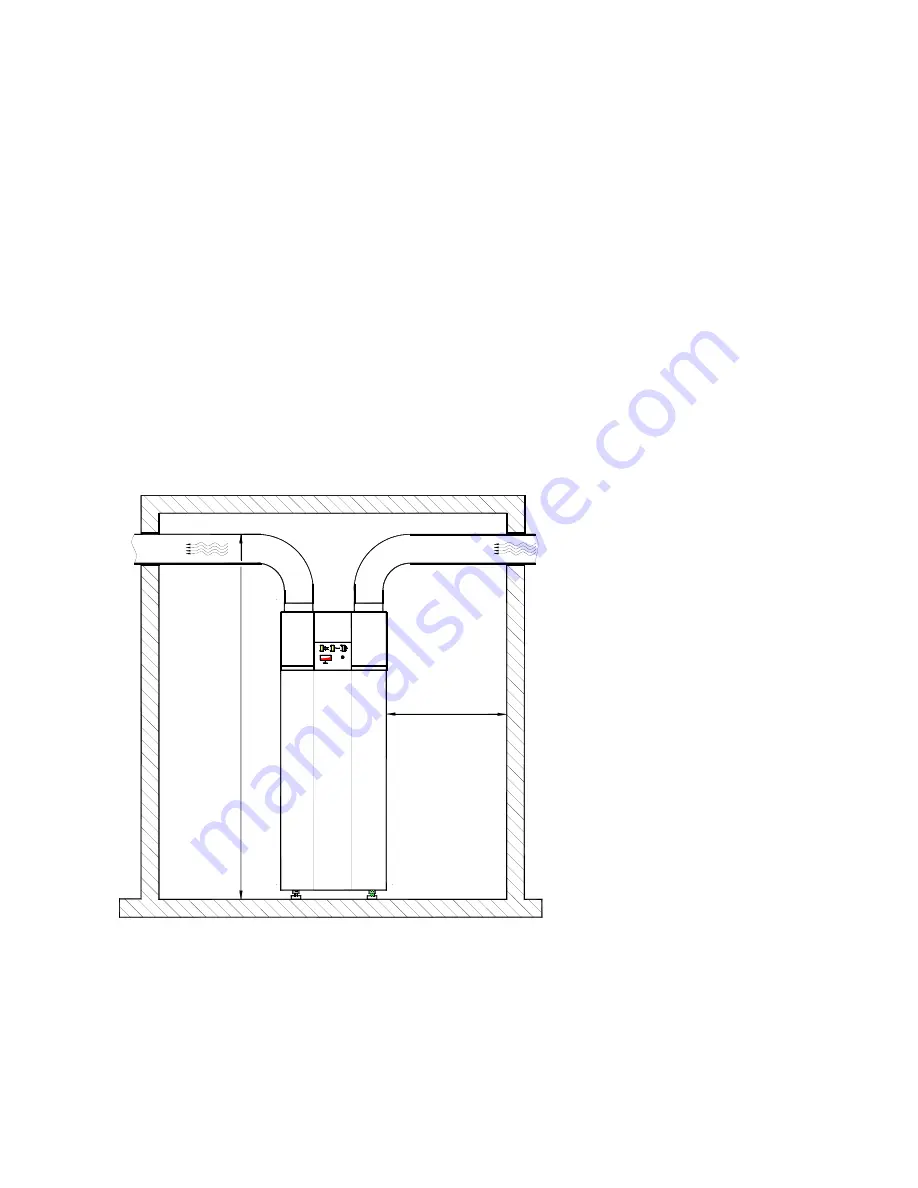
The notices below apply to the connection of the HPWH to exhaust air duct systems:
Standardised exhaust air systems:
Standardised exhaust air distribution systems with decentralised outside air valves are offered for use with the
HPWH. The connection of these systems to the unit is accomplished via a flexible, sound and heat insulated
airduct (DN 160). This airduct is employed for both exhaust air and outlet air.
The mounting instructions of the individual exhaust air system must be observed.
Where it can be expected that the operating noise of the system is transmitted into the rooms from which the
odour- and moisture-laden air is to be removed (e.g. in the case of very short air duct runs) a suitable duct
silencer (DN 160) is to be mounted on the exhaust-air side of the compact residential ventilation unit in addition.
Customised exhaust air systems:
If the exhaust air system uses rigid ductwork (e.g. spiral-wound ducting, flat ducts), a flexible transition (e.g.
flexible tubing with a total length of approx. 1m) should be selected for vibration decoupling purposes between
duct network and the exhaust air and outlet air pipe connectors of the unit).
On the exhaust air side, a suitable duct silencer should be used in order to avoid any transmission of the
operating noise of the ventilation unit.
Important notices:
- Suitable exhaust air filters should always be provided in the airduct system to prevent any contamination of the
unit and the heat exchangers.
- The outside of the exhaust ducting network should always be provided with diffusion-resistant insulation to
protect it from heat losses and the formation of condensation water if they ducts are routed through rooms (e.g.
attic, basement, etc.) that are colder than the room from which the waste air was exhausted.
Fig. 4: Installation requirements
4.2 Installation
¾
From the underside of the pallet, remove the three M12 bolts securing the pallet to the unit as a shipping
safety measure.
¾
Remove the pallet and mount the three levelling feet (M12 bolts – contained in the polybag, secured to the
storage tank pipe nipple).
¾
Site the HPWH and adjust the unit so that it is perpendicular by adjusting the levelling feet! Then tighten the
check nuts provided on the levelling feet.
( 0.6 m maintenance and
service clearance spaces
all around the unit )
( Wartungs- und
Servicefreiraum
allseitig um das
Gerät )
ca. 2,0 m
0,6 m
Abluft
Fortluft
Outlet air
Exhaust air
approx. 2.0 m


