


9
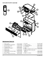
top cover: 2 on the left; 2 on the right; 2 on the back.
Remove the top, placing it upside down on the top of
the unit being careful not to damage any of the wiring.
Locate the flame speed control board mounted on the
5.
top panel and disconnect the wiring connections noting
their original locations.
!
NOTE:
Using a flat head screwdriver gently pry be
-
tween the end of the connector and the controller to release
the wires.
Pull off the flame speed control knob to expose the
6.
mounting nut.
Remove the mounting nut from the control arm of the
7.
flame speed controller.
From under the panel, break off the four mounting
8.
studs on the flame speed control board, push the re
-
mainder of the studs out through the top panel.
!
NOTE:
New mounting studs are supplied with the
replacement speed control.
Remove the flame speed control board.
9.
Properly orient the new flame speed control board and
10.
secure it to the unit with the included plastic mounting
studs.
Connect all of the wiring connections to the new board.
11.
Install the new controller to the front of the top cover
12.
with mounting nut and put the knob on the control arm.
Align the top cover with the cabinet assembly and se-
13.
cure with 6 retaining screws.
Place the firebox in the mantel.
14.
Place trim back on firebox by pushing ball studs on trim
15.
into the retainer clips on the firebox.
FLICKER MOTOR/FLICKER ROD
REPLACEMENT
Tools Required:
Phillips head screwdriver
Wire Cutters
Slip Joint Pliers
WARNINg:
If the fireplace was operating prior to
servicing allow at least 10 minutes for light bulbs and
heating elements to cool off to avoid accidental burning
of skin.
WARNINg:
Disconnect circuit power before attempt-
ing any maintenance or cleaning to reduce the risk of
electric shock or damage to persons.
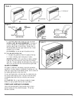
Remove the firebox trim by placing your hand on the
1.
grille section, grasping the sides of the trim and pulling
forward, away from the firebox, releasing the retainer
clips.
Remove the front glass, retaining clip.
2.
Remove the front glass and set aside.
3.
Remove the log set by lifting up the front edge of the
4.
log until it clears the front tabs. Pull out until the rear
tab clears the back ledge, then lift out.
!
IMPORTANT:
Only handle the log-set by the plastic
ember-bed, not the logs themselves.
!
NOTE:
Log-set fits tightly into firebox. Some force
may be necessary to remove.
Remove the firebox from the mantel and unplug.
5.
Remove 2 screws from the bottom panel located on the
6.
edge of the back assembly.
Lay unit on it’s back.
7.
Remove the 4 remaining screws from the bottom panel:
8.
2 located on the left and 2 located on the right sides.
Remove the bottom panel and set aside.
9.
Remove the screw from the motor bracket located in
10.
the flame panel, inside the unit on the left.
Remove flicker motor assembly by pulling flicker motor
11.
towards you and by removing bracket from slot located
in back panel.
Remove 2 screws securing the flicker motor to the
12.
flicker motor bracket.
Cut and strip off approximately 1/2” on the flicker motor
13.
wires at the flicker motor end.
Remove reflector rod from flicker motor by bending the
14.
rod down 90º and cutting the reflector spring with wire
cutters. (Read NOTES below).
CAUTION:
DO NOT TAKE THE LEFTOVER SPRING
OFF OF THE END OF THE REFLECTOR ROD.
!
NOTE:
Some units are equipped with a black rubber
cylinder connecting the flicker rod to the motor, if this is the
case there is no need to cut the spring, just gently pull the
assembly apart.
Discard old flicker motor.
15.
On the new flicker motor, cut and strip the wire leads to
16.
approximately 3 ½” long with wire cutters.
Using the provided wire connectors, place the yellow
17.
wires, one into each terminal (total of 2 yellow wires).
Secure wire connector by crimping the 3M symbol with
18.
slip joint pliers.
Pull on end of wires to ensure a strong connection.
19.
Repeat this process for the 4 remaining wires. (Red,
20.
blue, orange, grey)
!
NOTE:
ENSURE THAT ALL CONNECTORS HAVE
THE SAME WIRE COLORS
Pick up the black rubber cylinder and push the smaller
21.
end onto the new motor shaft and the larger end onto
the rod and spring.
!
NOTE:
Ensure the flicker motor bracket is in between
the motor and the reflector rod.
Reassemble in the reverse order.
22.
Summary of Contents for DF2600
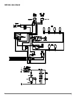
Page 7: ...7 WIRING DIAGRAM ...