


4
www.dimplex.com
MAINTENANCE
WARNINg:
If the fireplace was operating prior to
servicing allow at least 10 minutes for light bulbs and
heating elements to cool off to avoid accidental burning
of skin.
WARNINg:
Disconnect circuit power before attempt-
ing any maintenance or cleaning to reduce the risk of
electric shock or damage to persons.
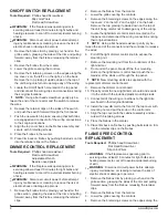
Light Bulb Replacement
Light bulbs need to be replaced when you notice a dark
section of the flame or when the clarity and detail of the
log exterior disappears. There are two bulbs at the top of
the opening, which illuminate the log set exterior, and four
bulbs under the log set which generate the flames and
embers.
Tool Requirements:
Philips head Screwdriver
!
NOTE:
Before replacing lamps unnecessarily, ensure
that they are not simply loose or that the brightness control
is not adjusted to low setting (see item D in operation
section).
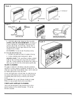
A. To open the light bulb area:
(Figure 4)
Remove the trim by pulling straight forward.
1.
Hold the glass in place while removing the retaining
2.
clip from the upper center of the firebox.
Lift glass out and store in a safe place.
3.
CAUTION:
Even though the glass is safety glass it
may break if bumped, struck or dropped. Care must be
taken when handling the glass.
HELPFUL HINTS:
It is a good idea to replace all light
bulbs at one time if they are close to the end of their
rated life. Group replacement will reduce the number of
times you need to open the unit to replace light bulbs.
B. To replace the bottom light bulbs:
(Figure 5)
Lift up the front edge of the log until it clears the
1.
front tabs. Pull out until the rear tab clears the back
ledge, and then lift out.
Examine the bulbs to determine which bulbs require
2.
replacement.
Hold the socket while unscrewing the bulb
3.
Hold the socket while screwing in the new bulb.
4.
Replace the log by pushing it down and in until it
5.
rests against the Partially Reflective Glass.
LOWER LIgHT BULB REQUIREMENTS:
Quantity
of 4 clear chandelier or candelabra bulbs with an E-12
(small) socket base, 60 watt rating.
CAUTION:
Do not exceed 60 watts per bulb.
C. To replace the top light bulbs:
(Figure 6)
Locate the two upper bulbs inside the firebox at the
1.
top.
Examine the bulbs to determine which bulbs require
2.
replacement.
Hold the socket while unscrewing the bulb
3.
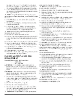
Remote Control Initialization/Reprogramming
If the Remote Control or Remote Control Receiver has
been replaced, follow these steps to initialize the Remote
Control and receiver:
Ensure that power is supplied through main service
1.
panel.
Locate manual controls (Figure 1).
2.
Activate On/Off Switch, (“─” position) (the red indicator
3.
light 1 may flash, depending on unit).
Press and hold the 3-Position Switch for five seconds
4.
(“─” position) UNTIL the middle red indicator light
flashes.
Press ON button located on the left of the Remote
5.
Control (Figure 3). This will synchronize the Remote
Control and receiver.
Remote Control Operation
The Remote Control operates the fireplace levels
sequentially. The level is increased every time the ON
button on the Remote Control is pressed. The fireplace
can be turned off at any point by pressing the OFF button
on the Remote Control.
Level 1
: The flame effect is turned on and the first
red indicator light turns on.
Level 2 :
The flame effect remains on, the heater is
activated to the low heat setting, and the first and second
red indicator lights turn on.
Level 3 :
The flame effect remains on, the heater is set
to the high heat setting, and all three red indicators will be
turned on.
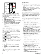
Battery Replacement
To replace the battery:
Slide battery cover open on the Remote Control
1.
(Figure 3).
Install one (1) 12-Volt (A23) battery in the battery
2.
holder.
Close the battery cover
3.
Battery must be recycled or disposed of properly.
Check with your Local Authority or Retailer for
recycling advice in your area.
Figure 3
Off Button
On
Button
Plastic
Strip
Battery
Cover
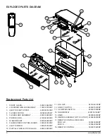
Summary of Contents for DF2600
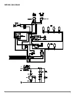
Page 7: ...7 WIRING DIAGRAM ...