


8
www.dimplex.com
ON/OFF SWITCH REPLACEMENT
Tools Required:
Phillips head Screwdriver
Slip Joint Pliers
Flat Head Screwdriver
WARNINg:
If the fireplace was operating prior to
servicing allow at least 10 minutes for light bulbs and
heating elements to cool off to avoid accidental burning
of skin.
WARNINg:
Disconnect circuit power before attempt-
ing any maintenance or cleaning to reduce the risk of
electric shock or damage to persons.
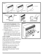
Remove the firebox trim by placing your hand on the
1.
grille section, grasping the sides of the trim and pulling
forward, away from the firebox, releasing the retainer
clips.
Remove the firebox from the mantel.
2.
Lower the grille covering the controls.
3.
Remove the 6 retaining screws on the edges along the
4.
top cover: 2 on the left; 2 on the right; 2 on the back.
Remove the top, placing it upside down on the top of
the unit being careful not to damage any of the wiring.
Locate the On/Off Switch mounted on the top panel
5.
and disconnect the wiring clips and connections noting
their original locations.
!
NOTE:
Using a flat head screwdriver gently pry be
-
tween the end of the connector and the switch to release
the wires.
Depress the retainer clips on the sides of the switch
6.
and push the switch forward through the front panel.
Push the new switch in place, ensuring that both tabs
7.
are engaged and connect all of the wiring connections
to their original locations.
Align the top cover back on the firebox assembly and
8.
secure with 6 retaining screws.
Place the firebox in the mantel.
9.
Place trim back on firebox by pushing ball studs on trim
10.
into the retainer clips on the firebox.
DIMMER CONTROL REPLACEMENT
Tools Required:
Phillips head screwdriver
Flat Head Screwdriver
Adjustable Wrench
Needle nosed pliers
WARNINg:
If the fireplace was operating prior to
servicing allow at least 10 minutes for light bulbs and
heating elements to cool off to avoid accidental burning
of skin.
WARNINg:
Disconnect circuit power before attempt-
ing any maintenance or cleaning to reduce the risk of
electric shock or damage to persons.
Remove the firebox trim by placing your hand on the
1.
grille section, grasping the sides of the trim and pulling
forward, away from the firebox, releasing the retainer
clips.
Remove the firebox from the mantel.
2.
Lower the grille covering the controls.
3.
Remove the 6 retaining screws on the edges along the
4.
top cover: 2 on the left; 2 on the right; 2 on the back.
Remove the top, placing it upside down on the top of
the unit being careful not to damage any of the wiring.
Locate the light dimmer control knob mounted on the
5.
top panel and disconnect the wiring connections noting
their original locations.
!
NOTE:
Using a flat head screwdriver gently pry be
-
tween the end of the connector and the controller to release
the wires.
Pull off the light dimmer control knob to expose the
6.
mounting nut.
Remove the mounting nut from the control arm of the
7.
light dimmer.
From under the panel, break off the four mounting
8.
studs on the light dimmer control board, push the re-
mainder of the studs out through the top panel.
!
NOTE:
New mounting studs are supplied with the
replacement dimmer control board.
Remove the dimmer control board.
9.
Properly orient the new light dimmer board and secure
10.
it to the unit with the included plastic mounting studs.
Connect all of the wiring connections to the light dim-
11.
mer board in their original locations.
Install the new dimmer to the front of the top cover with
12.
mounting nut and put the knob on the control arm.
Align the top cover with the cabinet assembly and se-
13.
cure with 6 retaining screws.
Place the firebox in the mantel.
14.
Place trim back on firebox by pushing ball studs on trim
15.
into the retainer clips on the firebox.
FLAME SPEED CONTROL
REPLACEMENT
Tools Required:
Phillips head Screwdriver
Flat Head Screwdriver
Slip Joint Pliers
WARNINg:
If the fireplace was operating prior to
servicing allow at least 10 minutes for light bulbs and
heating elements to cool off to avoid accidental burning
of skin.
WARNINg:
Disconnect circuit power before attempt-
ing any maintenance or cleaning to reduce the risk of
electric shock or damage to persons.
Remove the firebox trim by placing your hand on the
1.
grille section, grasping the sides of the trim and pulling
forward, away from the firebox, releasing the retainer
clips.
Remove the firebox from the mantel.
2.
Lower the grille covering the controls.
3.
Remove the 6 retaining screws on the edges along the
4.
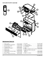
Summary of Contents for DF2600
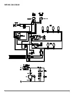
Page 7: ...7 WIRING DIAGRAM ...