


8
www.dimplex.com
on its right side (with the switches at the bottom).
Remove the 2 screws from the upper back panel,
7.
located approximately 5 ½ inches down from the top of
the insert, (This is on your left side if facing the back of
the unit while on its side). These screws hold the back
part of the heater housing to the insert.
While carefully holding the heater housing from the
8.
front, remove the 2 screws from the top panel of the
insert which hold the top of the heater housing to the
insert.
!
NOTE:
There are wires still attached to the heater
housing once the screws are removed.
Carefully lay the firebox insert on its back and pull the
9.
heater housing, with the heater assembly still attached,
out from the front of the firebox.
Move the heater housing 45 degrees and rest it on the
10.
work surface just beside the firebox.
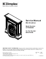
Remove the 4 screws which mount the heater assem-
11.
bly to the housing. This will allow you to remove the
heater assembly out of the housing so that you can
access the switches inside. (Figure 6)
Locate the defective switch mounted to the heater
12.
housing and disconnect the wiring clips and connec-
tions noting their original locations.
!
NOTE:
A flat head screwdriver can be used to gently
pry between the end of the connector and the switch to
release the wires.
Depress the retainer clips on the rear of the switch and
13.
push the switch out of the heater housing.
Properly orient the new switch and reconnect all of the
14.
wiring clips and connections.
Reassemble in the reverse order as above
15.
HEATER ASSEMBLY REPLACEMENT
Tools Required:
Phillips head Screwdriver
Flat Head Screwdriver
WARNINg:
If the fireplace was operating prior to
servicing allow at least 10 minutes for light bulbs and
heating elements to cool off to avoid accidental burning
of skin.
WARNINg:
Disconnect power before attempting any
maintenance or cleaning to reduce the risk of electric
shock or damage to persons.
Remove the nut and washer which secure the front trim
1.
to the mantel from behind (Figure 3).
Remove the front trim by pulling it away from the front
2.
of the mantel.
Remove the mesh curtains & rod from the mantel by
3.
pulling them away from the mantel, and set them aside
(Figure 5).
Remove 2 screws from the front of the fireplace which
4.
secure the firebox to the mantel base. These 2 screws
are in the bottom front of the firebox to the left and right
side (Figure 2).
From behind the mantel, remove 11 screws which se-
5.
cure the firebox to the mantel (Figure 3).
Remove the firebox from behind the mantel and lay it
6.
on its right side (with the switches at the bottom).
Remove the 2 screws from the upper back panel,
7.
located approximately 5 ½ inches down from the top of
the insert, (This is on your left side if facing the back of
the unit while on its side). These screws hold the back
part of the heater housing to the insert.
While carefully holding the heater housing from the
8.
front, remove the 2 screws from the top panel of the
insert which hold the top of the heater housing to the
insert.
!
NOTE:
There are wires still attached to the heater
housing once the screws are removed.
Carefully lay the firebox insert on its back and pull the
9.
heater housing, with the heater assembly still attached,
out from the front of the firebox.
Move the heater housing 45 degrees and rest it on the
10.
work surface just beside the firebox.
Remove the 4 screws which mount the heater assem-
11.
Figure 6
Heater Housing
Heater Assembly
Switches
Figure 7


