Dimplex CFP4949BW Service Manual Download Page 5

5

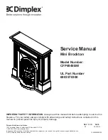
EXPLODED PARTS DIAgRAM

Replacement Parts List


POWER CORD 

1. 

 . . . . . . . . . . . . . . . . . . 4100090104RP

FLICKER MOTOR

2. 

. . . . . . . . . . . . . . . . . 2000210200RP

LIGHT HARNESS/ SOCKET

3. 

 . . . . . . . . 4200121000RP

PARTIALLY REFLECTIVE GLASS

4. 

. . . . 5900860100RP

REMOTE CONTROL RECEIVER

5. 

. . . . . 3000380200RP

REMOTE CONTROL

6. 

 . . . . . . . . . . . . . . 3000370500RP

3-POSITION SWITCH

7. 

 . . . . . . . . . . . . . 2800071100RP

HEATER SWITCH

8. 

. . . . . . . . . . . . . . . . . 2800070900RP

HEATER ASSEMBLY

9. 

 . . . . . . . . . . . . . . 2200491200RP

MINI-BROCKTON TRIM

10. 

. . . . . . . . . . . . 6905840184RP

CAPACITOR

11. 

. . . . . . . . . . . . . . . . . . . . . 2300030100RP

TERMINAL BLOCK

12. 

. . . . . . . . . . . . . . . . 4000070100RP

FLICKER ROD CONNECTOR

13. 

 . . . . . . . 8500680100RP

FLICKER ROD

14. 

 . . . . . . . . . . . . . . . . . . . 5900890100RP

LOG SET

15. 

. . . . . . . . . . . . . . . . . . . . . . . . 0440090100RP

3

4

5

9

10

8

7

13

12

11

1

6

2

14

Summary of Contents for CFP4949BW

Page 1: ...implex North America Limited Dimplex North America Limited 1367 Industrial Road Cambridge ON Canada N1R 7G8 1 888 346 7539 www dimplex com REV PCN DATE 00 20 JAN 12 IMPORTANT SAFETY INFORMATION Always...

Page 2: ...l result in damage to the equipment Warning Procedures and techniques which if not carefully followed will expose the user to the risk of fire serious injury or death OPERATION 3 MAINTENANCE 4 EXPLODE...

Page 3: ...ler for recycling advice in your area OPERATION MANUAL CONTROLS A 3 Position Switch The switch has two On positions marked with I and II The I position is for manual operation In this position the bui...

Page 4: ...ot of bracket Pull forward to clear bracket Remove the defective lamp s by unscrewing counter 4 clockwise Replace with a 60 Watt E12 clear chandelier or 5 candelabra Take care not to over tighten the...

Page 5: ...P REMOTE CONTROL RECEIVER 5 3000380200RP REMOTE CONTROL 6 3000370500RP 3 POSITION SWITCH 7 2800071100RP HEATER SWITCH 8 2800070900RP HEATER ASSEMBLY 9 2200491200RP MINI BROCKTON TRIM 10 6905840184RP C...

Page 6: ...6 www dimplex com WIRING DIAGRAM...

Page 7: ...otor 10 that secure the retaining bracket to the back panel the one that both the flicker motor and the light sockets are attached to Also remove the 2 screws directly above the rear left foot as well...

Page 8: ...g If the fireplace was operating prior to servicing allow at least 10 minutes for light bulbs and heating elements to cool off to avoid accidental burning of skin Warning Disconnect power before attem...

Page 9: ...cord out of the casing Connect the new power cord into the same location 12 Reassemble in the reverse order as above 13 REMOTE CONTROL RECEIVER REPLACEMENT Tools Required Phillips head Screwdriver Sli...

Page 10: ...er cord Replace power cord if cord gets hot to the touch Appearance Fireplace does not turn on Manu ally Improper operation Refer to Operation Section No incoming voltage from the electrical wall sock...

Page 11: ...the heater emits an odor for a brief period after the heater is initially turned on The heater is burning off any dust accumulated during manufacturing or operation Defective Heater Assembly Replace H...

Reviews: