background image

5. Getting Started 

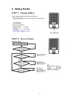
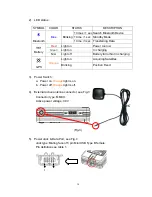
STEP 1. Charge Battery 

Please charge battery till LED off for the first time. 

Power cable plug in    Power cable connect to power socket 


Charge Battery 

Battery indicator light: 

Power too low 

--------

 red LED 


Charging -------------- green LED 

Full or Not in charging -- LED of


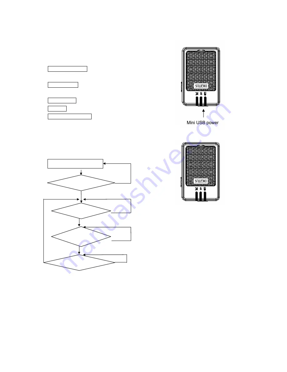
STEP 2. Turn on Power 

Bluetooth Status – 


Note: 

Some PDAs have to 

re-open Bluetooth 

manager for Bluetooth 

device re-connection.


Turn on DA-80200 power 

No

Searching 

Bluetooth device

Stop data 

transferring?

Data 

is transferring?

Reconnect 

Bluetooth device?

No

No

No

Yes 

Yes 

Yes 

Yes 

Blue LED blinking 

(1time / 1sec)


Transferring…

Blue LED blinking 

(1time / 3 sec)


Waiting for 

reconnection

… 

Blue LED blinking 

(1time / 1sec)


8

Summary of Contents for DA-80200

Page 1: ...User s Guide DA 80200 ...

Page 2: ...4 2 ACQUISITION TIME AVERAGED 6 4 3 RECEIVER ACCURACY 6 4 4 USE LIMITATION 6 4 5 POWER SUPPLY 6 4 6 OUTPUT AND INTERFACE 7 4 7 PHYSICAL 7 4 8 OTHER FUNCTIONS 7 5 GETTING STARTED 8 5 1 HARDWARE DESCRIPTION 9 5 2 SOFTWARE INSTALLATION 12 6 DRIVER INSTALLATION 13 6 1 SYSTEM REQUIREMENT 13 6 2 INSTALLATION 13 6 3 IMPORTANT 13 7 TROUBLE SHOOTING 13 ...

Page 3: ...oning application meets strict needs such as car navigation mapping surveying security agriculture and so on Only clear view of sky and certain power supply are necessary to the unit DA 80200 contacts to other device through Bluetooth device compatible interface or USB and built in recharge battery to save satellite information such as the status of satellite signal the last location date and time...

Page 4: ... you for a long time Before you begin make sure that your package includes the following items If any of these items are missing please contact your local dealer or distributor DA 80200 Wireless GPS receiver 1 Set Travel power supply Cigarette adapter 1 Set Manual and Driver CD 1 Piece DA 80200 Quick guide 1 Piece ...

Page 5: ... without external power supply and the working time lasts at least 10 hours Provide Continue mode and Power saving mode for user s requirement Provide expand terminal contact to other system without Bluetooth device Built in rechargeable battery for memory and RTC backup and for fast Time To First Fix TTFF Support NMEA0183 v2 2 data protocol and SiRF binary code 4 colors LED to show the status of ...

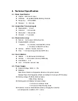
Page 6: ...ty within 0 1 meters second Time 1 microsecond synchronized GPS time 4 4 Use Limitation Altitude 18 000 meters 60 000 feet Velocity 736 meters second 1000Knots Acceleration 4 G Jerk 20 meters second max 4 5 Power Supply External Voltage 5VDC 10 Batteries Main Power Built in rechargeable Lithium ion for system power Backup Power Rechargeable Lithium ion battery for memory RTC backup Working voltage...

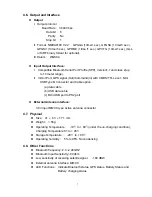
Page 7: ... Mini USB Type B Connector and Cable option a data cable b USB data cable c Mini USB port to PS2 port External Antenna interface 3 0V input MMCX type active antenna connector 4 7 Physical Size 41 63 17 1 mm Weight 56 g Operating Temperature 10 to 60 under the un charging condition Charging Temperature 0 to 45 Storage Temperature 20 to 85 Operating humidity 5 to 95 No condensing 4 8 Other Functions...

Page 8: ... Full or Not in charging LED of STEP 2 Turn on Power Bluetooth Status Note Some PDAs have to re open Bluetooth manager for Bluetooth device re connection Turn on DA 80200 power No Searching Bluetooth device Stop data transferring Data is transferring Reconnect Bluetooth device No No No Yes Yes Yes Yes Blue LED blinking 1time 1sec Transferring Blue LED blinking 1time 3 sec Waiting for reconnection ...

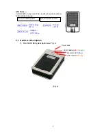
Page 9: ...e acquiring Search GPS Power Off Position Fixed Turn on DA 80200 power Turn off DA 80200 power Steady orange LED on Orange LED off Orange LED blinking 5 1 Hardware Description 1 DA 80200 Body description see Fig 2 Power Jack LED of Battery Red Green Bluetooth LED Blue LED of GPS Orange Fig 2 9 ...

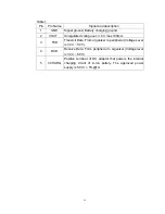
Page 10: ...CRIPTION 1 times 1 sec Search Bluetooth Device 1 time 1 sec Standby Mode Bluetooth Blue Blinking 1 time 3 sec Transferring Data Red Light on Power too low Green Light on In charging Battery N A Light off Battery full or Not in charging Light on Acquiring Satellites GPS Orange Blinking Position Fixed 5 Power Jack Data Port see Fig 4 Jack type Mating face of 5 pin Mini USB Type B female Pin definiti...

Page 11: ...tage out 3 6 V max 100mA 3 TXD Transmit Data From organizer to peripheral Voltage Level is 3 3V 5 0V 4 RXD Receive Data Form peripheral to organizer Voltage level is 3 3V 5 0V 5 VCHARG Positive terminal of DC adaptor that powers the internal charging circuit of Li Ion battery The approved power supply is 5 0V 5 1A ...

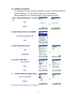
Page 12: ...r is one of popular program used for Bluetooth device 1 Open Bluetooth Manager on pocket pc New Connect 2 Search Bluetooth device DA 80200 Select Explore a Bluetooth device Next 3 Find the Bluetooth device Next Tap DA 80200 4 Connect to SPP Slave Select SPP slave Next Finish 6 5 Finish Bluetooth Manager Setup Tap and Hold DA 80200 Connect Finish Bluetooth setup opposite arrow is displayed 12 ...

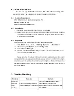
Page 13: ...Click Start menu select Setting then enter Controller II After entering Controller and select System III Select Device Manager IV Find the Connector COM LPT and check the Virtual COM Port which was created by the USB driver Please note that the virtual COM port number might be different from every computer Before using navigation software please confirm the COM Port numbers created by your compute...

Page 14: ... port Install DA 80200 incompletely or operate the device is being used with same COM port Install DA 80200 completely or stop other device that is being used Can not find out DA 80200 Poor connection Re Start PDA or PC and reference sec 5 2 re install software No action for few minutes may cause Pocket PC entry power save mode It will close the COM port at the same time Close the application and ...

Page 15: ...y one of the following measures Reorient or relocate the receiving antenna Increase the separation between the equipment and receiver Connect the equipment into an outlet on a circuit different from that to which the receiver is connected Consult the dealer or an experienced radio TV technician for help FCC Caution Any changes or modifications not expressly approved by the party responsible for co...

Page 16: ...device can cause radio interference in residential areas in this case the operator may be required to perform and bear the costs for appropriate measures Conformity Declaration The device fulfils the EMC requirements of EN 55022 class A for ITE and EN 55024 Devices with external or built in power supply also fulfil the requirements of EN 61000 3 2 and EN 61000 3 3 The basic protection requirements...

Reviews: