background image

5

8.  Foot Switch Release Pins 

- These two pins are spring-loaded 

hinges that hold the pedal in place. Push these pins in with the tip 

of a 1/4” guitar cable to release the pedal from the pedal chassis 

exposing the battery compartment. (See battery replacement 

diagram).

9.  Indicator LED

 - This LED indicates when the effect is turned on or 

off. When battery power is low (approximately 15 minutes before end 

of life), the Indicator LED begins to dim giving you advanced warning 

that very shortly you will need to replace the battery.

10.  Foot Switch

 - Press the Foot Switch to turn the effect on and off. 

11.  Output 1 (Mono)

 - Connect this output to the input of a single 

guitar amplifier, another pedal input, or an amp effects return. 

12.  Output 2 

- Connect this output to the input of a second guitar 

amplifier when a second amp is being used. 

Note: Use unbalanced mono instrument cables only.

Summary of Contents for HARDWIRE TR-7

Page 1: ...HARDWIRE TR 7 TREMOLO ROTARY OWNER S MANUAL...

Page 2: ...Directive 2002 96 EC EC Regulation 278 2009 With regard to Directive 2005 32 EC and EC Regulation 1275 2008 of 17 December 2008 this product is designed produced and classified as Professional Audio E...

Page 3: ...moisture 12 Refer to labels on the unit including bottom cover for other markings and pertinent information ELECTROMAGNETIC COMPATIBILITY This device complies with part 15 of the FCC Rules and the Pr...

Page 4: ...dered to be the responsibility of the consumer A copy of the original purchase receipt must be provided for any warranty service 5 DigiTech reserves the right to make changes in design or make additio...

Page 5: ...rs require Until battery technology advances to meet the requirements of digital pedals we suggest that a battery be used mainly for demonstration and practice purposes If you notice a change in the L...

Page 6: ......

Page 7: ...rior tone and control But these pedals go above and beyond their peers to provide such distinguishing features as true bypass and high voltage operation making them essential additions to the signal c...

Page 8: ...2 Pedal Interface 2 3 4 5 6 7 8 12 11 8 9 10 1...

Page 9: ...n power supply to this jack Use the proper supply for your area s mains line voltage 3 Depth Knob Controls the intensity of theTremolo Rotary effect Turn the knob clockwise for a deepTremolo Rotary so...

Page 10: ...ndicator LED may not be lit To prolong battery life disconnect all cables from the pedal when not in use If the optional power supply is used for power the input can remain connected 7 Input 2 Connect...

Page 11: ...When battery power is low approximately 15 minutes before end of life the Indicator LED begins to dim giving you advanced warning that very shortly you will need to replace the battery 10 Foot Switch...

Page 12: ...ying the power tube bias used in vintageVox amps DuoTrem Dual tremolos connected in series that interact with each other to create complex rhythm patterns Rotary Emulates a legendary LeslieTM rotary s...

Page 13: ...to VibroPan Speed Depth Pitch Phase The Speed 2 control affects the second tremolo speed Controls the amount of dry signal added to the effect Range is Chorus dry added min position toVibrato dry off...

Page 14: ...8 Amplifier Setup Harman Power Supply optional or...

Page 15: ...9 Effects Loop Setup AMP RETURN AMP SEND Harman Power Supply optional Note If the amp effects loop has a mix control set the mix to 100 full wet...

Page 16: ...push one of the Release Pins in on either side of the Foot Switch and remove it from the pedal chassis 2 Remove the battery from the battery compartment and disconnect the battery cable 3 Connect a n...

Page 17: ...e the pin When the Foot Switch is properly fastened both release pins are flush with the outer side of the pedal Foot Switch Pedal Switch Arm Foot Switch Release Pin 9VDC Battery Foot Switch Release P...

Page 18: ...Press and hold the Pedal Switch for 3 seconds The effect first will turn on and the Indicator LED lights solid BLUE NOTE If the effect was already on it will first turn off and then back on after 3 s...

Page 19: ...t been initiated after 4 seconds two taps will be required again to set the tempo 4 To exitTapTempo press and hold the Foot Switch for 3 seconds until the Indicator LED stops flashing and lights solid...

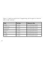
Page 20: ...te Modulation Rate Tremolo 1 second 4 Hz 4 beats per second OptoTremolo 1 second 4 Hz 4 beats per second BiasTremolo 1 second 4 Hz 4 beats per second DuoTrem 1 second 4 Hz 4 beats per second Rotary 1...

Page 21: ...e pedal into any pedal board a snap The following accessories are included Hook and loop Pedalboard Pad designed to attach to the surfaces found on most commercial pedalboards Foot Switch Glow Sticker...

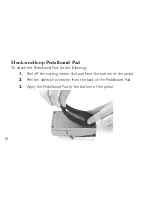
Page 22: ...o attach the Pedalboard Pad do the following 1 Peel off the existing rubber skid pad from the bottom of the pedal 2 Peel the adhesive protector from the back of the Pedalboard Pad 3 Apply the Pedalboa...

Page 23: ...17 Foot Switch Glow Sticker To attach the Foot Switch Glow Sticker do the following 1 Peel the adhesive backing from the Foot Switch Glow Sticker 2 Apply the Glow Sticker to the top of the Foot Switch...

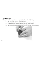
Page 24: ...ace the StompLock over the pedal knobs do the following 1 Set the knobs to your preferred setting 2 Gently push the StompLock over the top of the knobs 3 To remove the StompLock gently lift one side a...

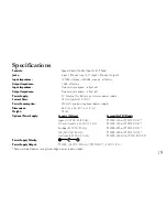
Page 25: ...typical at 9 VDC Power Consumption 640 mW typical w optional power supply Dimensions 5 25 L x 3 5 W x 2 15 H Weight 1 3 lbs Optional Power Supply Country Voltage Compatible PSU Models Japan 100 VAC 50...

Page 26: ......

Page 27: ......

Page 28: ...84070 PH 801 566 8800 FAX 801 566 7005 DigiTech and HardWire are registered trademarks of Harman Designed in the USA Copyright Harman Printed in China HardWire TR 7 Owner s Manual 5024343 B Please vi...

Reviews: