digitalview 41721003X-3 Instructions Manual Download Page 5

Specifications subject to change without notice 

© Digital View Ltd – Doc Ver 2.2:  12 Dec, 2011 (SVX-1920_manual.doc)  

Page 

4 of 67


ASSEMBLY NOTES


This controller is designed for monitor and custom display projects using 1920x1200 or 1920x1080 or 1600x1200 or 1680x1050 
or 1440x900 or 1366x768 or 1280 x 1024 or 1024 x 768 or 800x600 or 640x480 resolution TFT panels with a VGA, SVGA, 
WXGA, XGA, SXGA, UXGA or WUXGA signal input.  The following provides some guidelines for installation and preparation of 
a finished display solution. 
 

Preparation

: Before proceeding it is important to familiarize yourself with the parts making up the system and the various 

connectors, mounting holes and general layout of the controller.  As much as possible connectors have been labeled.  Guides 
to connectors and mounting holes are shown in the following relevant sections. 
 

1. 

LCD Panel

: This controller is designed for typical LVDS or TTL interfaced panels with panel voltage 3.3V, 5V or 12V, 

External for 12V~18V interface. Due to the variation between manufacturers of panels signal timing and other panel


characteristics, factory setup and confirmation should be obtained before connecting to a panel. 

(NOTE: Check panel 

power jumper settings before connection)


2. Controller

: Handle the controller with care as static charge may damage electronic components.  Make sure correct 

jumper and dip switches settings to match the target LCD panel. 


3. 

LCD signal cable (LVDS panel)

: In order to provide a clean signal it is recommended that LVDS signal cables are no 

longer than 46cm (18 inches). If those wire cabling is utilized these can be made into a harness with cable ties. Care 
should be taken when placing the cables to avoid signal interference. Additionally it may be necessary in some systems to 
add ferrite cores to the cable to minimize signal noise. 


4.

   Inverter

: This will be required for the backlight of an LCD, some LCD panels have an inverter built in.  As LCD panels may 

have 1 or more backlight tubes and the power requirements for different panel backlights may vary it is important to match 
the inverter in order to obtain optimum performance.  See Application notes page 25 for more information on connection. 


5.

   Inverter Cables

: Different inverter models require different cables and different pin assignment.  Make sure correct cable 

pin out to match inverter.  Using wrong cable pin out may damage the inverter. 


6. 

Function Controls

: The following section discusses the controls required and the section on connectors provides the 

detail.  The controls are minimal: On/Off, Backlight Brightness (depends on inverter), OSD (5 momentary buttons) analog 
VR type or (8 momentary buttons) digital type. 

        The 8 momentary buttons OSD switch mount P/N 416100520-3 or OSD membrane interface P/N 416100120-3 must be   
        used when 24VDC input.


7.

   Function controls cable

The cables to the function switches should be of suitable quality and length so that impedance 

does not affect performance.  Generally lengths up to 1 meter (3 feet) should be acceptable. 


8.

 Status 

LED

: The pin direction of the LED should be corrected for right colour indication.  Red colour stands for standby.  

Green colours stands for signal on.  The status LED is an optional part only, can be unconnected. 


9.

 IR 

sensor

: It is an optional part only, can be unconnected if not using IR remote control. See Appendix V in details. 

 
10.   RS-232 control interface : 

Firmware upgrade and serial control via this interface port. 


11.  Second RS-232 control interface :

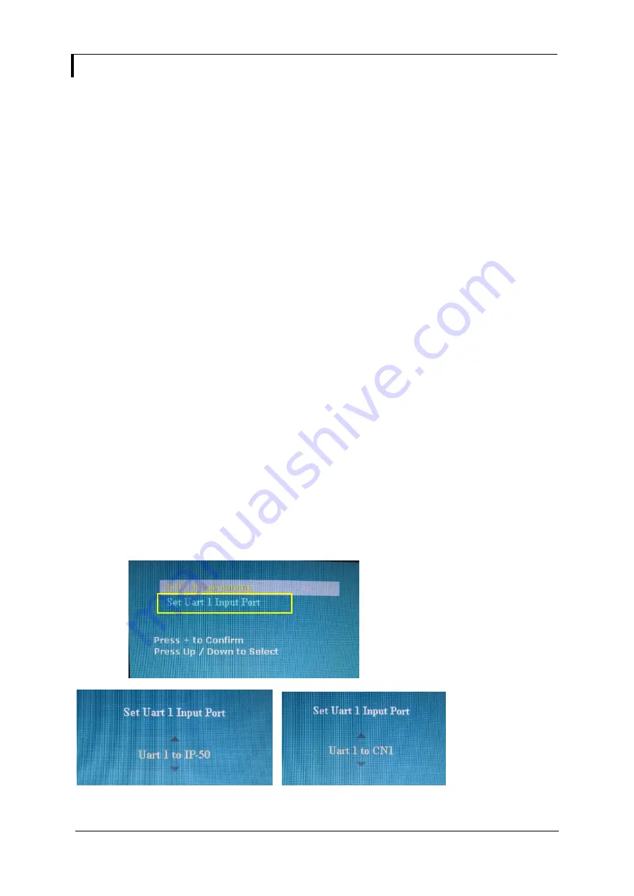
 This interface support controlled under “Programming mode” . 

       Press and hold “MENU” button on the OSD switch mount and turn on the controller to enter the “Programming mode”.   
       Choose “Set Uart 1 Input Port shown below : 

.                     


Set “Uart 1 to IP-50 : Enable Ethernet network (J1) support and disable second RS-232 serial control (CN1) support 
Set “Uart 1 to CN1 : Enable second RS-232 serial control (CN1) support. Disable Ethernet network (J1) support 

Summary of Contents for 41721003X-3

Page 1: ...ss mainly focus on the distribution of electronic components Line cards we deal with include Microchip ALPS ROHM Xilinx Pulse ON Everlight and Freescale Main products comprise IC Modules Potentiometer...

Page 2: ...27 Application notes 29 Troubleshooting 30 Specifications 31 Appendix I Supported graphics modes table 34 Appendix II RS 232 control protocols 51 Appendix III Mapping definition 55 Appendix IV Auto Co...

Page 3: ...0 P N 41721003X 3 P N 4172100XX 3 HOW TO PROCEED Ensure you have all parts that they are correct refer to Connection diagram Connector reference in following section Assembly notes Check controller sw...

Page 4: ...nal 10 RS 232 control interface 11 Second RS 232 control interface 12 External panel power output 13 Panel control signal 14 Audio add on board optional 15 Auxiliary 5VDC max 500mA output 16 Ambient l...

Page 5: ...l be required for the backlight of an LCD some LCD panels have an inverter built in As LCD panels may have 1 or more backlight tubes and the power requirements for different panel backlights may vary...

Page 6: ...he controller board This port is not supported when CN5 is connected 27 Analog RGB Input As this may affect regulatory emission test results and the quality of the signal to the controller a suitably...

Page 7: ...ables to prevent signal interference Heat Ventilation Heat generated from other sources for example the backlight of a very high brightness panel may generate significant heat which could adversely af...

Page 8: ...el specification and information on the jumper table to define the correct settings 9 VGA cable Controller Plug the VGA cable to the connector P1 on the controller board 10 Power supply Controller Plu...

Page 9: ...D menu page Menu button Menu button Select down Moves the selector to the next function down SEL DN SEL DN Select up Moves the selector to the previous function up SEL UP SEL UP Increase the OSD param...

Page 10: ...lower resolution image according to aspect ratio 4 3 scaling format in 4 3 16 9 scaling format in 16 9 16 10 scaling format in 16 10 2 35 1 scaling format in 2 35 1 2 1 scaling format in 2 1 1 1 Disp...

Page 11: ...dow will turn off automatically OFF PIP window keeps on DISPLAY WHEN SETTING ON UNDER SETUP AUTO SOURCE SEEK FUNCTION DISABLE WHEN KIT 70600 3 CONNECTED DISPLAY WHEN KIT 70600 3 CONNECTED Utilities Se...

Page 12: ...ype in the bezel opening area in horizontal with reference to the panel specification Bezel Opening Area V mm Type in the bezel opening area in vertical with reference to the panel specification Enabl...

Page 13: ...Defaults Resume to the default values 6500K Red Gain Green Gain Blue Gain Red Offset Green Offset Blue Offset Reset to Defaults Resume to the default values 8000K Red Gain Green Gain Blue Gain Red Of...

Page 14: ...mming control PWM dimming control Backlight Frequency 100 440Hz in a step of 20 Light Detector Enable ambient light detector function by using KIT 70220 3 Default Setting 4 Reset to Factory Defaults 4...

Page 15: ...ST 3 way B3B PH K Matching type PHR 3 CN10 HDMI audio Stereo output JST 4 way PHD 4 Matching type PHR 4 Matching audio cable P N 426451800 3 for connection to audio add on board P N 416940020 3 connec...

Page 16: ...13 40DS 1 25C IR1 Infra Red sensor connector JST 3 way B3B XH A Matching type XHP 3 LED1 Dual color LED connector Header pin 3x1 P1 VGA analog input DB 15 way high density 3 row P2 DVI D input DVI D c...

Page 17: ...y Defaults with Color Temp from OSD menu Position 7 Closed Enable for selection of the RM DN5 Assembly menu on Programming mode JC2 Custom configuration Position 1 Enable J3 pin 5 OP1 controlled by JB...

Page 18: ...N 1 3 2 4 5 7 6 8 CAUTION Incorrect setting can damage panel controller Input voltage via PP2 PP3 PP5 Panel Voltage JA3 JA5 JA6 Jumper on board 3 3V 3V3 closed 1 3 2 4 1 3 2 4 5V 5V closed 1 3 2 4 1 3...

Page 19: ...ge JA3 JA5 JA6 Jumper on board 3 3V OPEN 3 5 4 6 1 3 2 4 5V OPEN 3 5 4 6 1 3 2 4 12V OPEN 3 5 4 6 3 5 4 6 3 3 5 12 18VDC 18V OPEN 3 5 4 6 3 5 4 6 Maximum current for 3 3V 5V 7A Maximum current for 12V...

Page 20: ...nel OFF OFF OFF OFF Sharp LQ181E1LW31 1280x1024 ON OFF OFF OFF AU Optronics M170EN05 1280x1024 For XGA panel OFF OFF OFF OFF Sharp LQ150X1LGN2A 1024x768 Sharp LQ150X1LGB1 1024x768 For SVGA panel OFF O...

Page 21: ...tion ON LVDS panel OFF Reserved 4 LVDS data mapping select Refer to Table 2 If SW4 position 5 OFF 8 bit OFF Mapping B ON Mapping A Please adjust to get the correct picture See as Appendix I for detail...

Page 22: ...power supply for DDC optional 16 HPD Hot plug detect 17 DDC_CLK DDC Clock 18 DDC_DAT DDC Data 19 HS_IN Analog horizontal sync 20 GND Ground CN4 Panel connector HIROSE DF20G 10DP 1V Matching type DF20A...

Page 23: ...D 2 AUDIO LOUT HDMI LEFT OUT 3 GND GND 4 AUDIO ROUT HDMI RIGHT OUT CN11 SPDIF audio output connector JST B3B PH K Matching type PHR 3 PIN SYMBOL DESCRIPTION 1 SPDIF SPDIF Digital audio output 2 GND Gr...

Page 24: ...Green in 2 Ground 3 Cb Pb in_1 Blue in 4 Ground 5 Cr Pr in_1 Red in 6 Ground CNV5 Auxiliary Video input connector DIL socket header 13x2 PIN DESCRIPTION 1 S Video 1 Chroma in 2 Ground 3 S Video 1 Lum...

Page 25: ...data bit A4 12 TXA4 Negative differential LVDS data bit A4 13 TXAC Positive LVDS clock for A channel 14 TXAC Negative LVDS clock for A channel 15 TXB4 Positive differential LVDS data bit B4 16 TXB4 N...

Page 26: ...ection 5 NC No connection 6 DDC_CLK DDC Clock 7 DDC_DAT DDC Data 8 NC No connection 9 RX1 TMDS Data 1 10 RX1 TMDS Data 1 11 GND Digital Ground 12 NC No connection 13 NC No connection 14 DDC_5V 5V powe...

Reviews: