


Specifications subject to change without notice
© Digital View Ltd – Doc Ver 2.2: 12 Dec, 2011 (SVX-1920_manual.doc)
Page
11 of 67
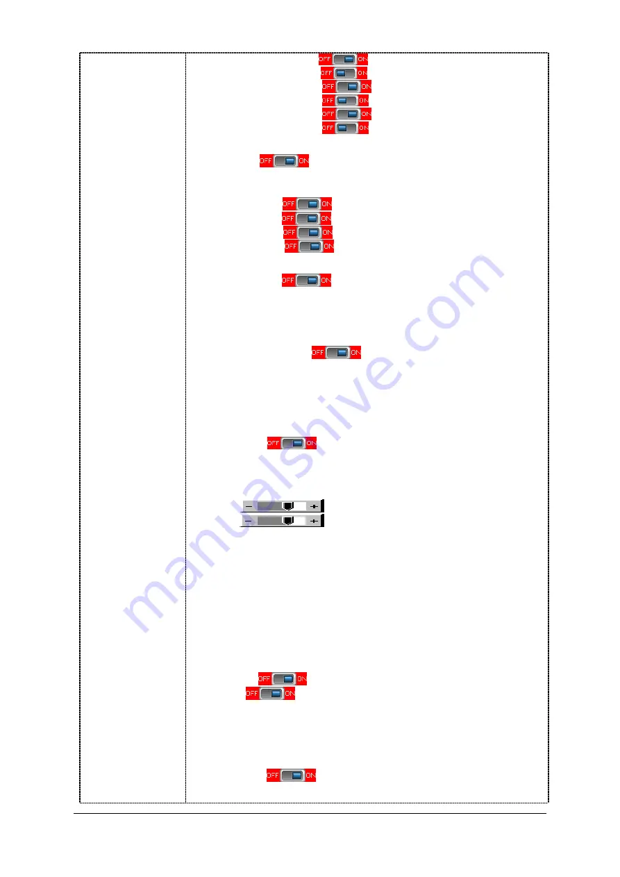
Composite 1
Composite 2
S-Video 1
S-Video 2
Component 1
Component 2
The corresponding input port name display on OSD menu will disappear once
setting “OFF”.
Auto Power :
OFF / ON
ON – Enable soft power off function if absence of input signals
OFF – Disable soft power function
De-interlacing Mode*
4
AFM
: Auto Film Mode
TNR
: Temporal Noise Reduction
MADI
: Motion Adaptive De-interlacing
DCDi
: Low Angled De-interlacing
[See Appendix VI for AFM, TNR, MADI, DCDi function description]
Video Wall Setup
4
Video Wall
Video Wall Size : Choose the video wall size (Number of panel for horizontal [max
4] x Number of panel for vertical [max 4]).
Video Wall ID Setup : Set the matching ID number same as the ID number shown
on screen. For details, please refer to the application note
of the video wall setup.
Bezel Compensation
4
Bezel Compensation
Active Area (H) (mm) : Type in the active area in horizontal with reference to the
panel specification
Active Area (V) (mm) : Type in the active area in vertical with reference to the panel
specification
Bezel Opening Area (H) (mm) : Type in the bezel opening area in horizontal with
reference to the panel specification.
Bezel Opening Area (V) (mm) : Type in the bezel opening area in vertical with
reference to the panel specification.
Enable RGB SOG:
OFF / ON
Video Standard (SD)* : Auto / NTSC / NTSC 4.43 / PAL / PAL M / SECAM
Gamma : 0.6 / 0.7/ 0.8 / 1.0 / 1.6 / 1.8 / 1.9 / 2.0 / 2.1 / 2.2 / 2.3 / 2.4 / 2.5 / 2.6 / User Setting
OSD
4
OSD position :
H POS
: Move the OSD menu image horizontally
V POS
: Move the OSD menu image vertically
OSD Timeout (sec) : ON – 60 : Adjust the OSD menu timeout period in a step of 5
seconds (max 60 seconds)
ON =
Continuous to display OSD menu.
60 = 60 seconds later will turn off the OSD menu.
Screen Marker
4
Screen Marker : On/Off
Center Marker : On/Off
Safe Area Enable : On/ Off
Aspect Marker Enable : On/Off
Safe Area Market : 80%~99%
Aspect Marker : 4:3 / 16:9
Transparency Level : 0% / 25% / 50% / 75% / 100%
Exit menu
Language : English / Spanish / French / German / Chinese :Select OSD menu language display
Transparency :
OFF / ON : Set OSD transparency
Display Input :
OFF / ON : Display input source info after switching source.
Real time clock
4
show and edit the real time clock (This function is valid when “Display Input”
sets ON.)
DATE : DD/MM/YYYY : Date/Month/Year
TIME : HH/MM/SS (AM/PM): Hour/Minute/Second
SETUP
4
Month / Day / Year
Hour / Minute / AM/PM
Display Clock
: Disable or enable to display the real time clock when
display video source info after switching source.


