background image


1-7

Installation Continued

Features

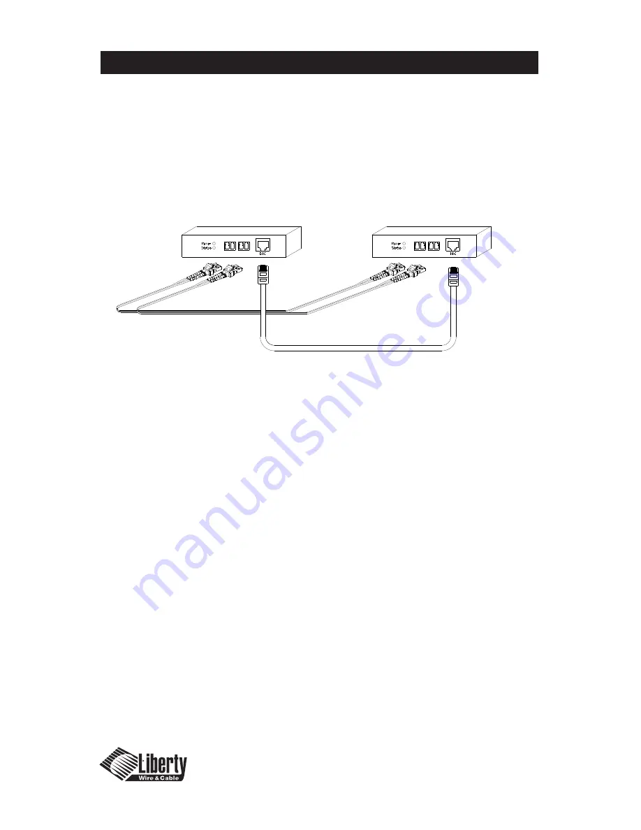
4.)  Remove the dust covers from the Fiber Optic LC receptacles and connect each 

Duplex LC cable one by one to each of the four LC receptacles.  Plug A to A and 

B to B.  Carefully recheck polarities and ensure the duplex connectors are fully 

engaged and locked in place.

5.)  Connect the RJ45 plug to each RJ45C receptacle of the TX  

and RX boxes.

6.)  Connect the DC power supply to either the TX or the RX unit depending on 

your availability of and AC power source.  This will power up both of the units.  

The power receptacle is located on the same side as the HDMI receptacle.  

Ensure both units have power by viewing the power LED.  SAFETY NOTE:  

Do NOT unplug the LC connectors and look directly into the connector or 

receptacle when operating.  This device is regulated as Laser Class 1 and severe 

eye damage can result.

7.)  Power up the Display side (Display can reference Media Receiver, Computer 

Monitor or Display).

8.)  Power up the Source side.

9.)  The Status LED on both the TX and RX units should be illuminated Green.  If it 

is not illuminated check the Polarity on the LC connectors.  Failure of the LED to 

illuminate can be caused by a poor fiber connection, broken fiber, or incorrect 

polarity on the LC plugs.

a.)  Tip – After initial power up shut down all displays and sources and repeat the 

start up operation

b.)  Do not “Hot Plug” the TX and RX units.  Ensure sources and displays are 

powered down prior to hookup.

10.)  Note:  It is recommended to use the longest run of cable between the source 

and the Fiber Optic Extender followed by a shorter run when possible to reap 

the greatest benefit of the signal boost.

11.)  The length of the HDMI or DVI cable on the source side should be 8 meters 

or less due to source signal inconsistencies.  The length from the RX unit to the 

display should be one size less then the source side.  For example an 8 meter 
cable on the source would have a 7 meter or shorter cable on the display side.

4

3

2

1

3

4

1

2

DL-HDFO TX Unit

DL-HDFO RX Unit

Installation Procedures Continued

4.) Remove the dust covers from the Fiber Optic LC receptacles and connect each Duplex LC cable

one by one to each of the four LC receptacles. Plug A to A and B to B. Carefully recheck
polarities and ensure the duplex connectors are fully engaged and locked in place.

5.) Connect the RJ45 plug to each RJ45C receptacle of the TX and RX boxes.

6.) Connect the DC power supply to either the TX or the RX unit depending on your availability of

and AC power source. This will power up both of the units. The power receptacle is located on
the same side as the HDMI receptacle. Ensure both units have power by viewing the power LED.

SAFETY NOTE:

Do NOT unplug the LC connectors and look directly into the connector or

receptacle when operating. This device is regulated as Laser Class 1 and severe eye damage can
result.

7.) Power up the Display side (Display can reference Media Receiver, Computer Monitor or Display).
8.) Power up the Source side.
9.) The Status LED on both the TX and RX units should be illuminated Green. If it is not illuminated

check the Polarity on the LC connectors. Failure of the LED to illuminate can be caused by a poor
fiber connection, broken fiber, or incorrect polarity on the LC plugs.

a.) Tip – After initial power up shut down all displays and sources and repeat the start up

operation

b.) Do not “Hot Plug” the TX and RX units. Ensure sources and displays are powered down

prior to hookup.

10.) Note: It is recommended to use the longest run of cable between the source and the Fiber Optic

Extender followed by a shorter run when possible to reap the greatest benefit of the signal boost.

11.) The length of the HDMI or DVI cable on the source side should be 8 meters or less due to source

signal inconsistencies. The length from the RX unit to the display should be one size less then the
source side. For example an 8 meter cable on the source would have a 7 meter or shorter cable on
the display side.

Page 1-7

Summary of Contents for DL-HDFO

Page 1: ...User s Manual Fiber Optic Extender Part DL HDFO ...

Page 2: ...roduct Description and General Specifications 1 5 Environmental Reliability Specifications 1 6 Installation Procedures 1 8 Mechanical Specifications 1 9 Technical Specifications 1 10 Warranty Information 1 11 Troubleshooting and Customer Service information TABLE OF CONTENTS Table of Contents ...

Page 3: ...ety Precautions 1 Please read all product manuals and safety notes prior to operating this or any devices 2 Retain the product manuals and safety notes for future reference 3 Unplug this unit prior to cleaning do not use liquid cleaners or aerosol cleaners Use a damp cloth for cleaning 4 Do not use this equipment near damp or wet locations 5 The product should only be powered by the indicated sour...

Page 4: ...turning the equipment on and off the user is encouraged t try to correct the interference by one or more of the following Re orient or relocate the receiving antenna Increase the separation between the equipment and the receiver Connect the equipment into an outlet on a circuit different from that to which the receiver is connected Consult a service representative for help Properly shielded and gr...

Page 5: ...t R G B and Clock with a copper Category 5 5e cable for DDC and power distribution This device can also be used to achieve plenum cabling possibilities for HDMI and DVI via the use of plenum rated Fiber Cable and Plenum rated Category 5 5e cable The system can easily accommodate DVI only inputs and outputs by using Liberty s high quality HDMI to DVI interconnects The DVI connector is routed to the...

Page 6: ...dity levels from 5 95 and an altitude ceiling of 15 000 meters 49 200 feet Environmental limits for storage are established as a temperature range of 20 C to 45 C non condensing humidity levels from 5 95 and an altitude ceiling of 3 000 meters 9 840 feet The Digitalinx Fiber Optic Extender is expected to function for more than 50 000 hours of use at a 90 confidence level The device is tested to th...

Page 7: ...ed and has been confirmed good 1 Carefully unpack the contents of the shipping package and verify all components are present 2 With all components powered down HDMI source and Display connect the TX box to the HDMI source using a copper HDMI interconnect cable from 1 8 meters in length 3 With all components powered down HDMI source and Display connect the RX box to the HDMI Display using a copper ...

Page 8: ...e on the source would have a 7 meter or shorter cable on the display side 4 3 2 1 3 4 1 2 DL HDFO TX Unit DL HDFO RX Unit Installation Procedures Continued 4 Remove the dust covers from the Fiber Optic LC receptacles and connect each Duplex LC cable one by one to each of the four LC receptacles Plug A to A and B to B Carefully recheck polarities and ensure the duplex connectors are fully engaged a...

Page 9: ...een 1 4 LC Receptacles for R G B and Clock DDC RJ45 Receptacle Power DDC CEC and HDCP Mechanical Specifications 4 3 2 1 Mechanical Specifications Dimensions DL HDFO TX and RX Units HxWxD 19mm x 38mm x 72mm HDMI IN HDMI from digital media source TX only HDMI OUT HDMI to digital video display RX only LED Power 12 VDC power Indicator LED Status Fiber Optic status indicator green 1 4 LC Receptacles fo...

Page 10: ...ernal power from DC Adapter HDCP High bandwidth Digital Content Protection Compliant Technical Specifications Connector pin assignment for HDMI Type A receptacle Pin Description 1 TMDS Data 2 2 TMDS Data 2 shield 3 TMDS Data 2 4 TMDS Data 1 5 TMDS Data 1 shield 6 TMDS Data 1 7 TMDS Data 0 8 TMDS Data 0 shield 9 TMDS Data 0 10 TMDS Clock 11 TMDS Clock shield 12 TMDS Clock 13 CEC 14 RESERVED 15 SCL ...

Page 11: ...ent products may be new or reconditioned Any replaced or repaired product or part has a ninety 90 day warranty or the remainder of the initial warranty period whichever is longer Liberty Wire Cable shall not be responsible for any software firmware information or memory data loss of customer contained in stored on or integrated with any products returned to Liberty Wire Cable for repair under warr...

Page 12: ...nd display The resolution must be less then or equal to UXGA 60HZ 2 Reboot the system in the correct sequence shown in the installation section of the manual 3 Power down disconnect and reconnect the optical connections and DC power adapters and power back up in the correct sequence No illumination Status LED 1 Check Polarity of LC Plugs Visually check fiber color codes to ensure LC cables were bu...

Page 13: ... 2007 Liberty Wire Cable All Rights Reserved Liberty Wire Cable 11675 Ridgeline Drive Colorado Springs CO 80921 800 530 8998 www libertycable com ...

Reviews: