Quick Start Guide for GPS150 V1.02
TEL + 44 1179 554474 www.digitalyacht.co.uk
4. Mode Selection
The GPS150 can be operated in a number of different
modes, for example;
GPS at 4800 baud for legacy systems
GPS+GLONASS at 38400 baud for new plotters
“Turbo Mode” at 115K baud for PC race software
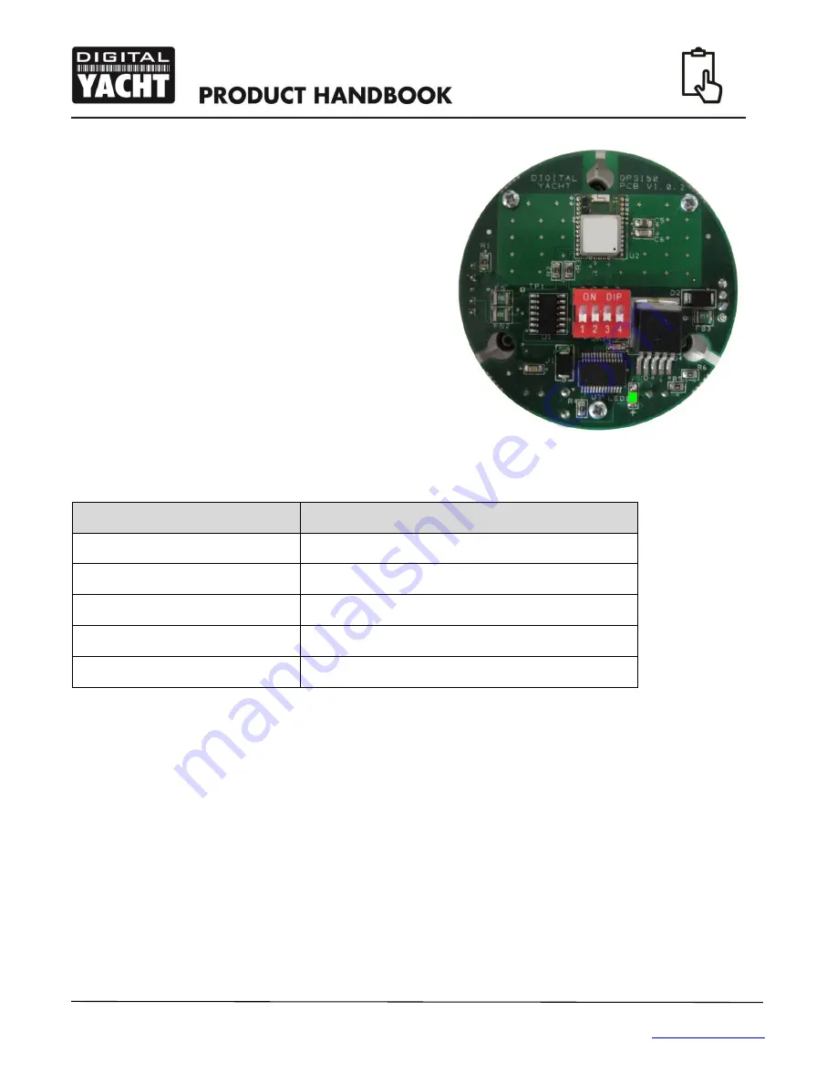
Selection of the operating mode is via four “DIP” switches
inside the unit. Changes to the switches will become
active when the GPS150 is power cycled (turned off/on).
There is a green LED on the PCB that indicates if the
GPS is working correctly and the baud rate selected. The
photo of the PCB shows the location of the LED and
switches.
Within 2-3 seconds of applying power to the GPS150, the LED should illuminate as follows;
LED State
Description
LED ON
Configured correctly for 4800 baud
LED Slow Flash
Configured correctly for 38400 baud
LED Quick Flash
Configured correctly for 115K baud (Turbo Mode)
LED Flashes once every 2 seconds
Unused Mode Selected (check DIP switches)
LED Flashes twice every 2 seconds
Power Up Sequence Failed*
* NOTE
– In some situations, where the switching of the power to the GPS150 is not cleanly made or it is made to quickly
(not giving the internal voltages time to dissipate), the GPS150 Power Up Sequence may fail resulting in the selected
operating mode not being setup correctly. This situation is indicated by the LED flashing twice every 2 seconds. Should
this occur, simply turn off the GPS150 wait 10 seconds and then power it up again. If it continues to not power up
correctly then contact Digital Yacht for further advice,
To access the switch, it is necessary to open the GPS150. It is recommended that this operation is only carried out by an
approved Digital Yacht Dealer/Distributor, any physical damage to the PCB will not be covered by warranty.
Before opening the GPS150, turn off all DC power to the unit and then remove the threaded mount by unscrewing the
3xM3 hex bolts using a suitable Allen Key. Then using a Torx T6 screwdriver, remove the three screws that hold the GPS
enclosure together. Gently pull the enclosure apart being careful not to lose the O-Ring seals (1 large outer and 3 small
screw pillar O-Rings).
Once the GPS150 PCB is exposed, set the four switches to the relevant positions for the required operating mode as
shown in the table on the next page
.
Summary of Contents for GPS150
Page 1: ......


