


E-57
NOTE: This option is only available when
"Yes" is selected for "Use Point on Signal
Change?".
Even if “CANCEL” is executed, changes to “Set Reference Point”,
“Use Reference Point” and “Return to Factory Default” will not be
canceled.
* See "Tips on Adjusting Focus" on page E-31 for more information.
NOTE:
• Adjusted values in Ref. Lens Memory will not be returned to default by using the
Factory Default.
• To store adjusted values for each input source, use the Lens Memory.
NOTE: In the Link mode the Lens Memory feature is not available.
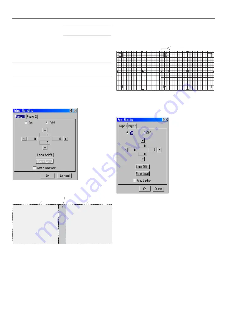
Edge Blending
When two or more projectors are used to project images lined up
horizontally or vertically, a blending adjustment can be performed
to make the borders of the adjacent images less conspicuous.
This description is of an adjustment example in which 2 Projec-
tors are used to project images side-by-side.
Preparation:
Set the lens position of each projector as close to centre as pos-
sible. If projection is not central in the lens then some image dis-
tortion may occur and images from two projectors may not be
successfully superimposed.
Making the image quality of each projector as uniform as pos-
sible will allow the screen edges (boundaries) to be less
conspicious.
- Installing the projector
Using the test pattern “Cross Hatch” in the projector, superim-
pose the images so that the height of the two projected images is
the same and distortion does not appear. If the number of pixels
in the superimposed area has been determined in advance, the
blending correction range can be easily adjusted in the following
bending correction.
- Adjusting the range of the superimposed area (blending correction range)
This adjustment is saved as Ref. Adjust data for the projector.
(1) Select “ON” in the [Edge Blending] - [Page 1] screen.
(2) From among the 4 location of
▲
marks on the [Edge Blending] -
[Page 1] screen, move the cursor to the
▲
mark that is the same
direction as the side on which you would like to perform blending
correction of the projector’s projection screen.
•
In the example above, select the
E
mark in the left projector to adjust
the right side of projected image, and select
F
mark in the right
projector to perform blending correction on the left side of the right
projector. Next press ENTER button.
(3) Perform blending correction for the left hand edge of the Right
projector.
Use
F
to adjust the blend of the Right projector and press ENTER.
•
To change the number of pixels in the superimposed area, input a
new value using the Remote Control numeric buttons, then press
ENTER.
If this value is not certain, align the marker on the projected image to
determine the blending range and press ENTER.
6. Using On-Screen Menu
Projected area
Projected area
Overlapping area
Overlapped cells
Summary of Contents for HIGHLite1400HD
Page 1: ...E 1 HL12000HD HL10000HD Super High Brightness Digital Video Projector User s Manual 104 744A...
Page 34: ...E 34...
Page 74: ...E 74...
Page 75: ...E 75 7 Maintenance 1 Cleaning the Cabinet and the Lens E 76...
Page 94: ...E 94...
Page 95: ...E 95...
Page 96: ...E 96...


