background image

060*(XVHUPDQXDOYHUVLRQ

3U&


7

8

9

10

5. Operation 

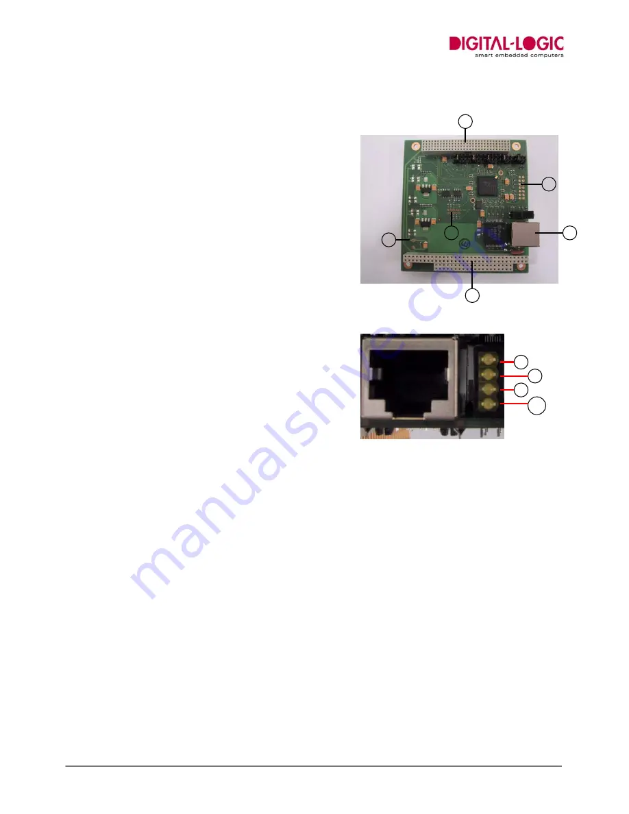
elements

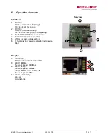
Interfaces

1. PC/104+

PCI bus connector stacktrough
30 x 4 pin, 2mm spacing

2. PC/104

ISA bus 16-bit stacktrough
32 x 2 and 20 x 2 pin, 2,54mm spacing

3.  RJ45 10/100/1000 Base-T connector
4.  Test connector, not assembled
5.  JTAG test port, not assembled
6.  3.3 volt auxiliary power connector, not assem-

bled

Display

7. LED 

SDP0

SDP0 Software Defined Pin LED

8. LED 

1000Mps

Network speed 1000Mbs

9.  LED 100 Mps

Network speed 100Mbs
LED 1000Mbs and 100Mbs off
Network speed 10Mbs

10.  LED Link / Activity

Link on
Activity blink

Top view

1

2

3

4

5

6

Summary of Contents for MSMGE104+

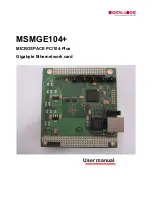
Page 1: ...MSMGE104 MICROSPACE PC 104 Plus Gigabyte Ethernetwork card User manual...

Page 2: ...tion 5 Trade marks 5 3 Extent of delivery 6 4 Introduction and description 7 PC 104 pheriperal board 7 Kommunikation 7 I O Ports 7 Power supply 7 Dimensions 7 5 Operation elements 8 Interfaces 8 Displ...

Page 3: ...ection The board is produced with high quality compo nents with long term availability Before delivery each device goes through a stress under hard conditions The product is not fully qualified by DIG...

Page 4: ...rranty is only granted when the device is not dismantled and is handed over or sent to the responsible sales agency in original packing together with sales slip or invoice The operating system user so...

Page 5: ...orization of the manufacturer has to be obtained Possible examples are Military devices Safety relevant applications Safety relevant medical applications e g life preserving machines Xray devices brea...

Page 6: ...cted for eventual damages through transport For damages or de fects which are not notified to the manufacturer within 2 weeks from date of purchase any claim for warranty will expire The packaging inc...

Page 7: ...net 10 100 1000 Base T Controller INTEL GD82541GI I O Ports 1x 10 100 1000 Base T shielded RJ45 port PCI interface connector stackthrough ISA only 5V and ground connected connector stackthrough Power...

Page 8: ...mm spacing 3 RJ45 10 100 1000 Base T connector 4 Test connector not assembled 5 JTAG test port not assembled 6 3 3 volt auxiliary power connector not assem bled Display 7 LED SDP0 SDP0 Software Define...

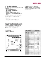
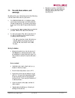
Page 9: ...ch should use different resources see jumper table Map of the board MSMGE104 Version 0 1 Plug the PC 104 CPU board to the MSMGE104 board Take care to properly align the connector before insertion do n...

Page 10: ...pheral cables are pluged in and out VGA Mouse Keyboard LAN ISDN Sound Strictly forbidden Bringing liquids onto or into the device If this happens by mistake the device must immediately be turned off a...

Page 11: ...sed WHICH application programs are installed ALL peripheral devices have to be mentioned Submit sales slip with purchase date Provide name of distributor and place of pur chase as well as description...

Reviews: