background image

-4-

3) Unscrew the two rear face

Blank Panel attachment
screws, and remove the Blank
Panel.

FDD’s Rear Blank (Filler) Panel

4) Attach the braket for PL-5911

Series that comes with the
FDD unit to the FDD unit and
secure it with the two (2)
attachment screws.

    The necessary torque is 0.5 to

0.6N•m.

    (Do not use the brank panel

removed in step 3).

(PL-5911T)

When using PL-5910
Series unit, be sure to use
the braket for PL-5910
Series.

Summary of Contents for PL-FD510

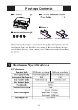
Page 1: ...he PL FD510 is an internally mounted 3 5 inch floppy disc drive unit designed for use with Proface s Panel Computer PL 5910 Series Units hereafter referred to as the PL Corresponding Product PL 5910 Series Units All product names used in this document are the trademarks of their respective manufacturers Pro face Digital Electronics Corporation PL FD510 Installation Guide WARNINGS To prevent this u...

Page 2: ...vice Attachment Screws 4 Performance 1 Hardware Specifications Operation Mode 2MB mode record write 1MB mode record write Disc Type 3 5 inch High density type 2HD Double density type 2DD Unformatted Data Capacity 2MB 1MB Data Transfer Speed 500K bits second 250K bits second Disc Rotation Speed Track Density Track track Seek Speed Atstart 0 7A typ Atread write 0 3A typ During wait 0 01A typ Reliabi...

Page 3: ...e 20o C to 60o C Ambient Humidity 20 RH to 80 RH no condensation Shock Resistance During shipping 980 7m s2 Vibration Resistance During operation 9 8m s2 10Hz to 25Hz 2 Installation Be sure to use the following installation procedures to insure that the unit is correctly installed As for PL 5910T unit the attachment procedures are same as PL 5911T unit WARNING Shock Danger Be sure to disconnect th...

Page 4: ...ller Panel 4 Attach the braket for PL 5911 Series that comes with the FDD unit to the FDD unit and secure it with the two 2 attachment screws The necessary torque is 0 5 to 0 6N m Do not use the brank panel removed in step 3 PL 5911T When using PL 5910 Series unit be sure to use the braket for PL 5910 Series ...

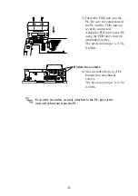
Page 5: ...the FDD unit to the PL using the FDD unit s four 4 attachment screws The necessary torque is 0 5 to 0 6N m 6 This includes the two 2 PL bottom face attachment screws The necessary torque is 0 5 to 0 6N m Even after the unit is securely attached to the PL part of the unit will extend out from the PL Bottom face screws ...

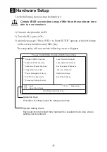
Page 6: ...eys Provides a list of keys used for setup procedures System Setting Areas Each selection item shown here represents a separate menu area where settings can be entered 4 Standard CMOS Features 4 Advanced BIOS Features 4 Advanced Chipset Features 4 Integrated Peripherals 4 Power Management Setup 4 PnP PCI Configurations 4 Frequency Voltage Control ESC Quit Select Item F10 Save Exit Setup Time Date ...

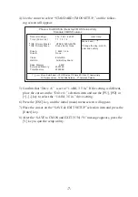
Page 7: ...e setup utility 4 Use the cursor to select STANDARD CMOS SETUP and the follow ing screen will appear Date mm dd yy Thu Feb 15 2007 Time hh mm ss 11 15 14 4IDE Primary Master HTS541020G9AT00 4IDE Primary Slave Press Enter None Drive A 1 44M 3 5 in Drive B None Video EGA VGA Halt On All But Keyboard Base Memory 640K Externded Memory 259072K Total Memory 260096K Move Enter Select PU PD Value F10 Save...

Page 8: ...r for any damages losses or third party claims arising from the uses of this product Inquiry Do you have any questions about difficulties with this product Please access our site anytime that you need help with a solution http www pro face com otasuke Copyright 2007 Digital Electronics Corporation ...

Reviews: