background image

OpenLogger™ Acrylic Case Assembly Manual

Copyright Digilent, Inc. All rights reserved.

Other product and company names mentioned may be trademarks of their respective owners.

Page

12

of

12

Step 8

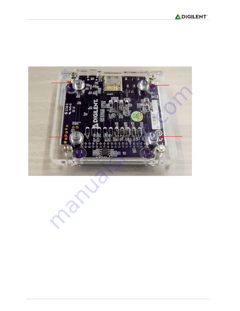
Once the nuts have secured the screws, turn the OpenLogger so that the bottom side is facing up. Remove backing
layer from rubber feet to expose adhesive. Place the rubber feet on the bottom of the case in each corner near the
nuts as shown in Figure 18. This completes the case assembly. Happy data logging!

Figure 18:Rubber FeetInstallation

Summary of Contents for OpenLogger 240-139

Page 1: ...opyright Digilent Inc All rights reserved Other product and company names mentioned may be trademarks of their respective owners Page 1 of 12 Table of Contents Table of Contents 1 Parts Description 2...

Page 2: ...any names mentioned may be trademarks of their respective owners Page 2 of 12 Parts Description Figures 1 through 4 are labeled pictures of the 4 acrylic layers that assemble the OpenLogger case Refer...

Page 3: ...ed Other product and company names mentioned may be trademarks of their respective owners Page 3 of 12 Figure2 LayerB Top Middle Figure3 LayerC Bottom Middle Note There are two notches in the top righ...

Page 4: ...names mentioned may be trademarks of their respective owners Page 4 of 12 Figure4 LayerD Bottom Table1 HardwareDescription Image Description Quantity Pan Head Phillips Screw Thread M3 x 0 5mm Length...

Page 5: ...Do not pick up the case until the hex nuts have been secured to the screws that hold all layers together Also note that each layer has a notch on one side to allow access to the microSD microUSB and p...

Page 6: ...ive owners Page 6 of 12 Step 2 Place Layer A face down with screws facing upward through the smaller set of four holes near the corners of the layer Use the edge of a table to assist with inserting al...

Page 7: ...ner than Layer C and has a larger open gap Once Step 3 is completed set it aside retaining orientation Do not pick it up off the table This part of the assembly will be integrated in Step 5 Figure8 Co...

Page 8: ...entioned may be trademarks of their respective owners Page 8 of 12 Figure10 OpenLoggeron LayerD Figure11 LayerC AroundOpenLogger Note Arrows indicate notch locations on Layer C Also refer to Figure 3...

Page 9: ...tep Place each assembly side by side as shown in Figure 12 Pick up the assembly from Step 4 flip it horizontally as shown in Figure 13 such that it is upside down Then place it on top of the assembly...

Page 10: ...s Step 6 Lift one corner of the case so that you can place a finger under the screw head as shown in Figure 15 Pick up a nut with your other hand to hand tighten the nut onto the screw as shown in Fig...

Page 11: ...ts have been hand tightened on each screw make sure all layers are flush against each other and along each edge They should not need to be forced into position Once proper assembly is confirmed use a...

Page 12: ...owners Page 12 of 12 Step 8 Once the nuts have secured the screws turn the OpenLogger so that the bottom side is facing up Remove backing layer from rubber feet to expose adhesive Place the rubber fee...

Reviews: