background image

DR4024 Servodecoder


P 12 

www.digikeijs.com 

® R-Bus, B-Bus


are trademarks which are registered in the name of Modelleisenbahn GmbH. XpressNet and RS-Bus is a trademark registered in the name of Lenz 

Stand 2018.10.22 

3.6 Reset DR4024 to Factory SeDngs (Programming Track) 

The reset via the programming track should only be done if the reset via the POM programming did not work. 
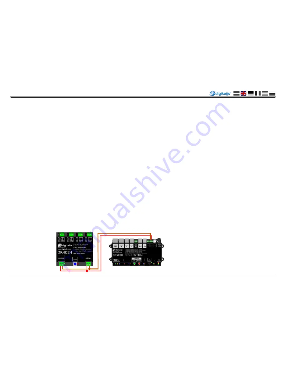
Connect the signal and power connec ons of the DR4024 to the programming track connec on of your control panel.  
Please note that reading out and programming the DR4024 via the programming track only works if the central unit does not switch off the programming track! 
Therefore, before a;emp ng programming, check that the green LED next to the power connector is lit. Only if this is the case can the DR4024 be successfully 
programmed as described in this sec on. 

If the green LED does not light up, refer to sec on 3.7 of this manual. 


1. 

Connect the signal and power connec1ons to the programming track of the control panel. 

2. 

Now check whether the green LED next to the power connector is permanently lit. 

If the green LED does not light up, refer to sec on 3.7 of this manual.


3. 

Press the programming bu2on on the DR4024. The red LED now lights up con1nuously and indicates that the DR4024 is in "programming mode".  
is located.  

4. 

Select the CV programming func1on via the programming track in your central, app or handset controller. 

(For further informa on on CV byte or CV bit programming, please refer to the opera ng instruc ons of your control panel)  

5. 

Now write the CV 8 with the decimal value 8 to reset the DR4024. 

6. 

Exit the programming mode by pressing the programming bu2on on the DR4024. 
The red LED goes out and indicates that the programming mode has been terminated. 

Important! 

Otherwise the DR4024 will restart in programming mode. 

7. 

Now disconnect the power and signal connec1ons from the programming track. 
 

A;en on! 

Wait approx. 30 seconds before powering the DR4024 again and restoring the siding. 

 
The DR4024 is now reset to factory seBngs. The POM address was reset to 9999 again and the DR4024 has the magne1c ar1cle address 1 again. By switching the 
magne1c ar1cle address 1 it can be checked whether the RESET was successful. 

Summary of Contents for DR4024

Page 1: ...n GmbH XpressNet and RS Bus is a trademark registered in the name of Lenz Stand 2018 10 22 DR4024 servo decoder instruction manual 2018 10 22 Copyright 2005 2018 digikeijs the Netherlands All rights reserved No informa1on images or any part of this document may be copied without the prior wri2en permission of Digikeijs ...

Page 2: ...rogramming 11 3 6 ReseBng the DR4024 to Factory Defaults programming track 12 3 7 Special feature CV programming for control panels which switch off the programming track 13 3 8 ReseBng the DR4024 to factory seBngs for Control panels which switch off the programming track 14 4 0 Troubleshoo ng 15 4 1 The red LED goes out again even though the programming bu2on was not pressed again 15 5 0 Connec on ...

Page 3: ... void the warranty ATTENTION The warranty is void if the housing of the product is opened 1 3 Legal informa on Prin1ng errors and mistakes technical or other changes as well as changes in the availability of individual products are expressly reserved Data and illustra1ons are non binding All changes to hardware firmware and soJware are reserved We reserve the right to change the design of the produ...

Page 4: ...ses and much more The DR4024 switches off the control of the servos when the posi1on is reached thus guaranteeing that no unnecessary power is consumed 2 2 Technical specifica ons The connec1on terminals for power and signal track voltage are designed for a cross sec1on of 0 5mm Number of Outputs Protokoll Loading Capacity Out 5 Out 8 Load capacity of the servo outputs power supply voltage DR4024 4 ...

Page 5: ...tput 5 3 Connec1on S2 Servo 2 Output 2 4 Connec1on Out 6 Output 6 5 Connec1on S3 Servo 3 Output 3 6 Connec1on Out 7 Output 7 7 Connec1on S4 Servo 4 Output 4 8 Connec1on Out 8 Output 8 9 Power Anschluss Recommenda1on min 12V DC 2A 10 Green LED Display Supply voltage present 11 programming bu2on 12 Red LED Display programming mode glows constantly Display switching command is executed lights up as l...

Page 6: ...ic informa on about programming the DR4024 Please pay a en on to these points as otherwise the programming may fail or errors may occur CV programming is always possible on the programming track if available Some command sta1ons switch off the programming track which makes programming the DR4024 on the programming track somewhat more diffi cult With some central units it comes with the readout of CV ...

Page 7: ... address at the central unit handset controller app etc 2 Press the programming bu2on on the DR4024 the red LED will light up con1nuously The decoder is now in programming mode 3 The next step is to switch the desired turnout address with the control panel the app or the handset control DR4024 as the start address 4 The programming mode is automa1cally terminated aJer switching the turnout address...

Page 8: ...24 The red LED now lights up con1nuously and indicates that the DR4024 is in Programming Mode is located The servo just actuated now moves to the neutral posi1on centre posi1on of the servo 7 Move the speed controller forwards or backwards and set the servo to the desired posi on A leJ posi1on A 8 Switch the F1 func1on on the speed controller on and off again to save this posi1on A in the DR4024 Im...

Page 9: ...he locomo1ve in the control panel 3 Press the programming bu2on on the DR4024 The red LED is now lit con1nuously and indicates that the DR4024 is in programming mode 4 Select the CV Programming POM func1on in your control panel app or handset For further informa on on CV byte or CV bit programming please refer to the opera ng instruc ons of your control panel 5 Now the desired CV value can be wri2...

Page 10: ...e defined in the central unit mul1 mouse app etc The DR4024 can be programmed similar to a locomo1ve decoder using this locomo1ve address 4 Select the locomo1ve with the address 9999 at the central sta1on mul1 mouse app etc Switch the func1on F0 light on and off again to ac1vate the locomo1ve in the control panel 5 Press the programming bu2on on the DR4024 The red LED is now lit con1nuously and indi...

Page 11: ... to ac1vate the locomo1ve in the control panel 3 Press the programming bu2on on the DR4024 The red LED now lights up con1nuously and indicates that the DR4024 is in programming mode is located 4 Select the CV Programming POM func1on in your control panel app or handset For further informa on on CV byte or CV bit programming please refer to the opera ng instruc ons of your control panel 5 Now write...

Page 12: ...check whether the green LED next to the power connector is permanently lit If the green LED does not light up refer to sec on 3 7 of this manual 3 Press the programming bu2on on the DR4024 The red LED now lights up con1nuously and indicates that the DR4024 is in programming mode is located 4 Select the CV programming func1on via the programming track in your central app or handset controller For f...

Page 13: ...ould light up permanently 3 Now press the programming bu2on on the DR4024 The red LED will light to indicate that the DR4024 is in programming mode 4 Now disconnect the POWER and SIGNAL connectors from the main track Track Out 5 Now reconnect the POWER and SIGNAL connec1ons to the programming track of your control panel The green and red LEDs now go out because the programming track is not constan...

Page 14: ...k of your control panel The green and red LEDs now go out because the programming track is not constantly supplied with power The programming mode of the DR4024 remains unchanged 6 Select the CV programming func1on via the programming track in your central app or handset controller Further informa on on CV byte or CV bit programming can be found in the opera ng manual of your control panel To rese...

Page 15: ... central sta1on This can be easily avoided by always ac1va1ng the loco mo1ve with the address 9999 before pressing the programming bu2on of the DR4024 In order to avoid the red LED ex nguishing please observe the following procedure for POM programming 1 Define a locomo1ve with locomo1ve address 9999 DCC 128 speed steps in the central mul1 mouse or app 2 Ac1vate the locomo1ve with address 9999 in t...

Page 16: ...12V DC 2A 5 1 Connec on op ons Power and signal Connec on Signal Connec1on to main track Power Connec1on to an external power supply Recommended for normal opera on and for the POM programming Signal Connec1on to programming track Power Connec1on to programming track Signal Connec1on to main track Power Connec1on to main track Alterna1ve to connec1ng an external power supply Suitable for normal op...

Page 17: ...lleisenbahn GmbH XpressNet and RS Bus is a trademark registered in the name of Lenz Stand 2018 10 22 5 2 Connec on DR4102 relay switch polariza on DR4024 PRESET 1 DC Important Be sure to observe the polarity and of the DR4102 An incorrect connec1on will destroy the Out x switching out put on the DR4024 NO C NC ...

Page 18: ...us B Bus are trademarks which are registered in the name of Modelleisenbahn GmbH XpressNet and RS Bus is a trademark registered in the name of Lenz Stand 2018 10 22 5 3 Railway crossing with barrier and interchangeable indicators 5 4 Wing signal NL ...

Page 19: ... other cables to avoid interference Always make sure that the voltage source used can provide sufficient current A A switching power supply is be2er suited for this purpose than an old AC transformer Never twist the servo by hand This can cause damage to the gearbox of the servo The servo lever should always be mounted in the middle posi1on of the servo Observe point 3 2 of this manual Always ensure...

Page 20: ...witching outputs with bit 7 ac1ve in CV117 CV120 Value 20 is 90x per minute 0 255 20 113 116 CVs 113 116 have the same func1on as servos 1 4 0 255 2 Value Funk on 0 Default seBng 0 4 servos 1 4 and 4 separate switching outputs 5 8 8 addresses 1 Default seBng 1 4 servos 1 4 with linked switching outputs 1 4 4 addresses 2 Default seBng 2 4 servos with mass simula1on 1 4 and 4 separate switching outp...

Page 21: ...si1ons can be selected using func1on mapping see page 19 0 255 224 122 Posi1on C for servo 1 0 255 176 123 Posi1on B for servo 1 0 255 32 124 Posi1on D for servo 1 0 255 80 117 CVs 117 120 each have the same func1on as switching outputs 1 4 Switching output 1 OUT 5 Bits 0 1 sets the switching point for the on posi1on of the assigned switching output Bits 4 5 sets the switching point for the off pos...

Page 22: ...h when it is at the end posi1on For this to work the end posi1on BounceValue must be less than 255 and the end posi1on BounceValue more than 0 0 63 0 138 Mass Simula1on Value for Servo 2 see CV137 0 63 0 139 Mass Simula1on Value for Servo 3 see CV137 0 63 0 140 Mass Simula1on Value for Servo 4 see CV137 0 63 0 136 Posi1on D for Servo 4 0 255 80 135 Posi1on B for Servo 4 0 255 32 134 Posi1on C for ...

Page 23: ...73 1 2 4 8 16 32 64 128 OFF 174 175 176 1 2 4 8 16 32 64 128 Bu2on 7 ON 177 178 179 1 2 4 8 16 32 64 128 OFF 180 181 182 1 2 4 8 16 32 64 128 Bu2on 8 ON 183 184 185 1 2 4 8 16 32 64 128 OFF 186 187 188 1 2 4 8 16 32 64 128 The GREEN numbers are the default seDngs for SERVO 1 4 The RED numbers are the default seDngs for OUTPUT 5 8 7 1 Funk ons Mapping The following table shows you how to connect th...

Page 24: ...s are linked to the servo outputs The addi1onal switching outputs are switched as soon as the respec1ve servo reaches the middle posi1on Use this preset if you want to polarize a crossover via a relay DR4102 Preset 2 Preset 2 4 servos with mass simula1on 1 4 and 4 separate switching outputs 5 8 Default seBng 2 automa1cally gives the module 8 outputs Addr 1 4 are assigned for the 4 servo outputs S1...

Page 25: ...point on which to build other effects For example you can use preset 2 as the basis for a signal that influences the behavior of the locomo1ve Adjust the func1on mapping so that the outputs switch together with the servos and set the output configura1on so that it switches when the green mode is reached Important The servo speed and end posi1ons are not influenced by the presets Default seBng 3 Preset...

Reviews: