background image

P/N: RF160IRG  Rev 1.0  

Page  

  3

Copyright © 2021 


E&OE

RF Outputs

Solution 6000 control panels with firmware version 

2.53.18 and later now have the ability to add/delete and 

test RF outputs when using Digiflex Smart RF Receivers 

(PN: RF120 and/or RF121) via the following menu’s.

MENU 4-3-0 Add RF Device
MENU 4-3-1 Delete RF Device
MENU 4-3-2 Test RF Device

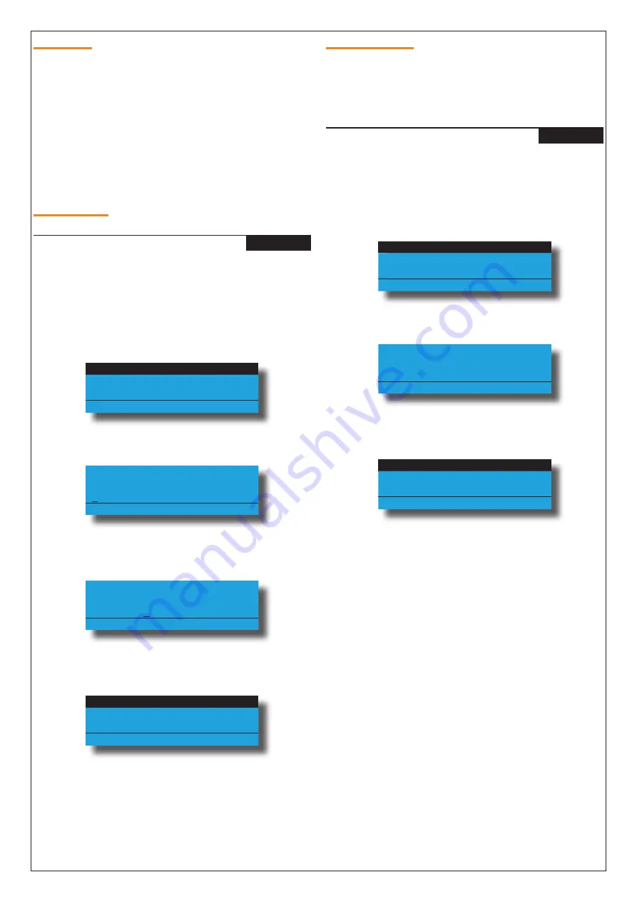
Add RF Device

Outputs > RF Output

Add RF Device

MENU  4-3-0

This menu allows the installer to learn relay 1 and/or relay 

2 of the RF160 module to operate an output configured 

at the control panel.
1) 

Press [MENU] + [4] + [3] + [0] and use the up and 

down arrows to highlight the output in the list, 

then press [OK]. 


Op1 External Siren

Op2 Strobe Light

Op3 Smoke Sensor PWR

Press 



 OK or MENU

2) 

The keypad will display the current RF160 ID.


Enter Device ID Op6

Garage Door

0000000000

Press OK or MENU

3) 

Press and hold both relay buttons on the RF160 

module to learn the RF ID.


Enter Device ID Op6

Garage Door

0F9105130 

Press OK or MENU

4) 

Press [OK] to save and exit or press [MENU] to exit 

without saving.


Relay 1

Relay 2

Exit

Press 



 OK or MENU

5) 

Select Relay 1 to use relay 1 or select Relay 2 to use 

relay 2 of the RF160 module, then press [OK to 

save and exit or press [MENU] to exit without 

saving.

Delete RF Device

This menu allows the installer to delete a relay on the 

RF160 module.  This menu does not delete the actual 

output configuration set at the control panel.

Outputs > RF Output

Delete RF Device

MENU  4-3-1

This menu allows the installer to delete relay 1 and/or 

relay 2 of the RF160 module.
1) 

Press [MENU] + [4] + [3] + [1] and use the up and 

down arrows to highlight the output in the list, 

then press [OK]. 


Op1 External Siren

Op2 Strobe Light

Op3 Smoke Sensor PWR

Press 



 OK or MENU

2) 

The keypad will display the current RF160 ID.


Delete Device ID Op6

Garage Door

0F9105130 Ch1

Press OK or MENU

3) 

Press [OK] to delete and exit or press [MENU] to 

exit without saving.


Relay 1

Relay 2

Exit

Press 



 OK or MENU

4) 

Select Relay 1 to use relay 1 or select Relay 2 to use 

relay 2 of the RF160 module, then press [OK to 

save and exit or press [MENU] to exit without 

saving.


Summary of Contents for RF160

Page 1: ...Installer Reference Guide RF160 2 Channel SMART RF Wireless Output Module 433MHz Rev 1 0 RoHS ...

Page 2: ...xposed to moisture or high humidity Reception distances are generally improved with higher mounting locations and with no metal ob jects near the unit If range is not achievable due to environmental or specification limitations then look at relocating the unit to a more appropriate location Receiver Operation The RF160 will turn on the green RX LED to indicate the unit is powered and it will blink...

Page 3: ...or 0F9105130 Press OK or MENU 4 Press OK to save and exit or press MENU to exit without saving Relay 1 Relay 2 Exit Press OK or MENU 5 Select Relay 1 to use relay 1 or select Relay 2 to use relay 2 of the RF160 module then press OK to save and exit or press MENU to exit without saving Delete RF Device This menu allows the installer to delete a relay on the RF160 module This menu does not delete th...

Page 4: ...oke Sensor PWR Press OK or MENU 2 The keypad will display the current RF160 ID Op6 Garage Door Waiting for Trigger Press OK or MENU 3 Press and hold both relay buttons on the RF160 module to transmit a packet signal Op6 Garage Door Rx3 Packets 001 v2 02 Signal Good 247 Press OK or MENU 4 Press OK or press MENU to exit The keypad will display the receiver address that re ceived the packet signal fr...

Page 5: ...ion Diagram Connection Diagram Antenna connects here Relay 1 terminal connections are used to connect to a 3rd party device Relay 2 terminal connections are used to connect to a 3rd party device Relay 1 and Relay 2 can be manually operated by pressing their respective buttons Power input A C or D C 9 28 V ...

Page 6: ... a terminal cover The top cover is fixed to the base using a Phillips head screw The top cover needs to be removed to install the wire antenna The terminal cover is a press fit allowing easy removal Once the wiring and programming has been completed the cover should be reinstalled to help prevent the ingress of insects and other debris Wall Mounting A wall mounting tab is located on the inside of ...

Page 7: ...ision X Solution 6000 V2 53 18 or higher Dimensions 114mm W 128mm W with Mounting Tab 62mm D 28mm H Environment 0 to 49 C Indoors Fixing Method Using mounting screws fix unit on a vertical surface in portrait orientation Relay Outputs Contact Rating 1A 30V D C Warranty 3 years from date of manufacture return to base RoHS In the interest of ongoing product development this document is subject to ch...

Page 8: ... Digiflex Pty Ltd P N RF160IRG Rev 1 0 DIGIFLEX PTY LTD 18 Brumby Street Seven Hills NSW 2147 AUSTRALIA Phone 612 97417000 Email sales digiflex com au www digiflex com au Our Vision Is Your Peace Of Mind Made in Australia ...

Reviews: