Digga HP450 Operator'S Manual Download Page 21

OPERATING INSTRUCTIONS


DEEP CUTS


To achieve a deep cut the width of the drum, make the first cut at the recommended depth for the material 
being  milled  and  then  reposition  the  profiler  at  the  beginning  of  the  pass  and  reset for  double  the 
recommended depth.  

Example: Make the first cut with the depth controls set at 50mm and then set the depth control at 100mm 
for the second pass and so on and so forth until the desired depth is obtained. To achieve a 150mm cut 
of a large area it is recommended to cut the entire area at the recommended depth and then clear the 
spoil from the area before making the second cut.  

Removing the spoil between cuts will enhance the productivity of the profiler and maintain an even cut. 
If trying to achieve a critical cutting depth it is recommended that the spoil from one cut be cleared away 
before making another pass. This will eliminate the possibility of the profiler riding on and off the spoil 
and creating an uneven surface.
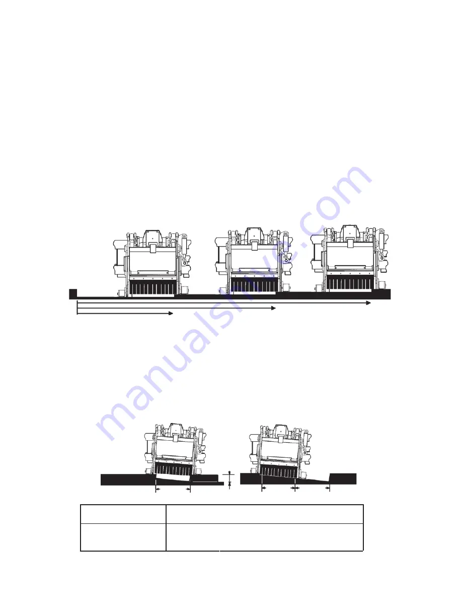
 

REMOVE SPOIL 

AFTER


3rd PASS


REMOVE SPOIL 

AFTER


2nd PASS


REMOVE SPOIL 

AFTER


1st PASS


3rd PASS


2nd 
PASS


1st PASS


MILLING TAPER CUTS


When adding to or joining new paved surfaces to existing paving, a taper cut may be required at the 
interacting joints so the new paving would appear seamless. See the chart below for the angle of cut 
per size of 

road profiler.

Example: 

To  achieve a taper cut from 0-100mm  over a 1200mm  distance  with a 600mm  wide  road 

profiler it is recommended that you set one side of the profiler at 50mm and the other at 100mm and the 
tilt set at 4° for the first pass. Then make a second pass with both sides of the p

rofiler

 set at  0mm and 

the tilt still at 4°.


1st 

PASS


100mm


2nd 

PASS


1st 

PASS


MODEL


25mm


ANGLE OF CUT PER OFFSET


50mm 

75mm 

100mm


450mm Road Profiler


N

/

A


600mm Road Profiler


N

/

A


PM-000068-A  DECEMBER 2017

19

Summary of Contents for HP450

Page 1: ...OPERATOR S MANUAL HP450 HP600 ROAD PROFILERS FOR SKID STEER LOADERS PM 000068 A DECEMBER 2017...

Page 2: ...THIS PAGE IS INTENTIONALLY BLANK PM 000068 A DECEMBER 2017...

Page 3: ...LICATIONS 18 19 Large Area Milling Around Manholes Deep Cuts Milling Taper Cuts STORAGE 20 LIFT POINTS 20 21 TIE DOWN POINTS 21 MAINTENANCE AND SERVICE LUBRICATION 22 ROUTINE MAINTENANCE 23 PICK REPLA...

Page 4: ...THIS PAGE IS INTENTIONALLY BLANK PM 000068 A DECEMBER 2017 2...

Page 5: ...safety with this equipment falls to the operator Make sure the equipment is operated only by trained individuals that have read and understand this manual If there is any portion of this manual or fun...

Page 6: ...nd the prime mover thoroughly before beginning installation operation or maintenance FOLLOW ALL SAFETY INSTRUCTIONS IN THIS MANUAL AND THE PRIME MOVER S MANUAL S READ AND UNDERSTAND ALL SAFETY STATEME...

Page 7: ...SSURE Hydraulic fluid under pressure can penetrate the skin and cause serious injury or death Hydraulic leaks under pressure may not be visible Before connecting or disconnecting hydraulic hoses read...

Page 8: ...or the job at hand Make sure they are in good condition for the task required Wear the protective equipment specified by the tool manufacturer SAFELY OPERATE EQUIPMENT Do not operate equipment until y...

Page 9: ...proved respirator If you use solvent or paint stripper remove stripper with soap and water before welding Remove solvent or paint stripper containers and other flammable material from area Allow fumes...

Page 10: ...he fuel tank for expansion Wipe up any spilled fuel Secure cap tightly when done MAINTAINING THE PROFILER Before performing maintenance lower the attachment to the ground turn off the engine remove th...

Page 11: ...ety decals clean and legible Replace all missing illegible or damaged safety decals When replacing parts with safety decals attached the safety decals must also be replaced REPLACING SAFETY DECALS Cle...

Page 12: ...ARNING HIGH PRESSURE FLUID PART 40151 WARNING PART 4468 WARNING READ MANUAL PART 40150 STAND CLEAR PART 40161 DANGER FLYING DEBRIS PART 40719 LARGE PART 40855 SMALL WARNING HAZARDOUS DUST PART 41043 S...

Page 13: ...ASE CONTROL HANDLE OPERATION CONTROLS PART 41197 NEW HOLLAND CONTROL HANDLE HP450 MODEL NUMBER HP450 18 PLANER PART 40791 HP600 MODEL NUMBER HP600 24 PLANER PART 40792 41196 RIGHT SHOE LEFT SHOE SIDE...

Page 14: ...SPHALT CAUSING HIGH LEVELS OF DUST IT IS RECOMMENDED TO USE DUST SUPPRESSION DUST COLLECTION AND IF NECESSARY PERSONAL PROTECTIVE EQUIPMENT DURING THE OPERATION OF THE PLANER OR OF ANY ATTACHMENT THAT...

Page 15: ...ous names of these components This knowledge will be helpful when reading through the manual or when ordering service parts SIDE SHIFT FRAME RIGHT DEPTH CYLINDER CONTROL VALVE VALVE COVER LEFT DEPTH C...

Page 16: ...he attachment onto the skid steer 4 Lower the unit to the ground and remove the key 5 Relieve any pressure from the auxiliary hydraulic system After making sure that there is not any foreign matter on...

Page 17: ...to 0 3 Set road profiler on a firm level surface 4 Following Safety Shut Down Procedures stop the engine and set the parking brake Relieve any pressure in the hydraulic lines 5 Disconnect the power a...

Page 18: ...side shift position of the profiler Best performance is obtained when the road profiler is in the center position Side shift should be used when visibility is a determining factor such as milling arou...

Page 19: ...ng on the rear wheel assemblies Continue to exert down pressure by rolling the loader forward until the front wheels of the profiler are on the ground and the front wheels of the skid steer are raised...

Page 20: ...ch side of the manhole NOTE The more passes the less amount of manual clean up required 1st PASS 1st PASS 2nd PASS 3rd PASS 3rd PASS MANUAL CLEAN UP AREA 4th PASS 2nd PASS MANHOLE OR BASIN 1st PASS PM...

Page 21: ...ut be cleared away before making another pass This will eliminate the possibility of the profiler riding on and off the spoil and creating an uneven surface REMOVE SPOIL AFTER 3rd PASS REMOVE SPOIL AF...

Page 22: ...he unit outside will materially shorten its live Additional Precautions for Long Term Storage Touch up all unpainted surfaces with paint to prevent rust REMOVAL FROM STORAGE Remove cover Wash unit and...

Page 23: ...ies around cylinders or in any way that may damage hoses or hydraulic components See Diagram Attach tie down accessories to unit as recommended Check unit stability before transporting WARNING VERIFY...

Page 24: ...of operation whichever comes last with SAE Multi Purpose Lubricant or equivalent SAE Multi Purpose type grease Lubricate weekly or every 40 house of operation whichever comes last with SAE Multi Purpo...

Page 25: ...as required Hydraulic Oil Check prime mover hydraulic system for adequate oil levels Hardware Check for tightness see Bolt Torque Specifications Hardware Replace any missing or damaged bolts or nuts...

Page 26: ...he drum until the pick to be removed is conveniently accessible 3 Hold the extracting tool pick puller in one hand and place the jaws in the groove of the pick with the offset handle pointing away fro...

Page 27: ...r off of the drum 4 Install the new drum by positioning it over the studs on the planetary and installing the existing M16 hex nuts using Locktite 271 Red and torquing to 210Nm 155 ft lbs 5 Reinstall...

Page 28: ...the correct position with the ports turned up Torque to specification 6 Reinstall the drum as described in CHANGING THE DRUM 7 Re connect the hydraulic hoses and fittings to the motor CHANGING HYDRAU...

Page 29: ...nd the bore of the cylinder tube for deep scratches or galling If damaged the piston AND the cylinder tube must bereplaced 3 Remove the hex nut piston flat washer or spacer tube if so equipped and gla...

Page 30: ...linder rod 5 Secure the cylinder rod mounting end in a vise with a support at its center Torque the nut to the amount shown for the thread diameter of the cylinder rod see chart IMPORTANT Do not conta...

Page 31: ...aged Insufficient power Insufficient hydraulic flow from the skid steer Relief valve setting adjusted too low Hydraulic motor damaged or seals blown Oil filter on skid steer is dirty Tighten or replac...

Page 32: ...wners manual Visually inspect the cylinder for damage Replace cylinder seals Remove obstruction and replace if necessary Refer to skid steer s owners manual All hydraulic cylinders not functioning Tes...

Page 33: ...7 90 1088 62 DESCRIPTION SPECIFICATTION A Overall Width mm B Overall Height mm C Overall Length mm D Planing Width mm E Planing Depth mm Drum Diameter Number of Picks Full size drum Weight Kg High Flo...

Page 34: ...49 1870 2236 2535 2686 3026 3642 4103 METRIC BOLT TORQUE SPECIFICATIONS NOTE The following torque values are for use with metric hardware that is unplated and either dry or lubricated with engine oil...

Page 35: ...equired for safe dependable operation To facilitate parts ordering when contacting the factory please have the model and serial number of your product ready to ensure that you receive the correct part...

Page 36: ...THIS PAGE IS INTENTIONALLY BLANK PM 000068 A DECEMBER 2017 34...

Page 37: ...ranty hereby provided a Option to Repair or Replace Digga Australia shall have the option to repair or replace the product b Timely Repair and Notice In order to obtain the Limited Warranty i the prod...

Reviews: