Planning the Installation
15.6-inch display
Copyright © 2021, Diebold Nixdorf01750342843C
8-2
Page 1: ...BEETLE A Series User Manual 01750342843C...
Page 2: ...ngs 4 1 4 1 Components 4 1 4 1 1 Processor Type 4 1 4 1 2 Memory Options 4 1 4 1 3 M 2 SSD Options 4 1 5 Setting Up the Device 5 1 5 1 Ergonomic Terminal Workplace 5 1 6 Overview 6 1 6 1 Front View wi...
Page 3: ...fan 11 1 11 2 Installing the fan 11 1 12 Storage Media 12 1 12 1 Whiskey Lake Sx motherboard 12 1 12 1 1 Replacement of Solid State Disk 12 1 12 1 2 Replacement of the RAM 12 3 12 2 Coffee Lake R3 R4...
Page 4: ...CR 15 16 15 5 1 Overview 15 16 15 5 2 Installation 15 17 15 5 3 Swivel angle 15 20 16 Starting Up the System 16 1 17 Error Reporting 17 1 18 POST Code 18 1 19 Technical Data 19 1 19 1 AC Power Adapter...
Page 5: ...n radiate radio frequency energy and if not installed and used in accordance with the in struction manual may cause harmful interference to radio communications Operation of this equipment in a reside...
Page 6: ...l Spanish Por medio de la presente declara que el dispositivo cumple con los req uisitos esenciales y cualesquiera otras disposiciones aplicables o exigi bles de la Directiva 2014 53 CE Greek Diebold...
Page 7: ...d Nixdorf t mto vyhlasuje e zariadenie sp a z kladn po ia davky a v etky pr slu n ustanovenia Smernice 2014 53 ES Suomi Finnish Diebold Nixdorf vakuuttaa t ten ett laite on direktiivin 2014 53 EY olee...
Page 8: ...de li cence L exploitation est autoris e aux deux conditions suivantes 1 L appareil ne doit pas produire de brouillage 2 L appareil doit accepter tout brouillage radio lectrique subi m me si le brouil...
Page 9: ...ability agreements Expansion cards with electrostatically sensitive devices ESD may be marked with this sticker CAUTION Hot surface Do not touch When opening the device or handling modules fitted with...
Page 10: ...plug disconnected and the Cus tomer Service of Diebold Nixdorf or your dealer must be notified Your Beetle A Series system is the result of modern technical innovation So please see for accord ing st...
Page 11: ...mperature surrounding environment can result in an explo sion or the leakage of flammable liquid or gas A battery subjected to extremely low air pressure may result in an explosion or the leakage of f...
Page 12: ...tact Information Diebold Nixdorf 5995 Mayfair Road N Canton OH 44720 USA Phone 1 330 490 5049 FCC Compliance Statement for products subject to Part 15 This device complies with Part 15 of the FCC Rule...
Page 13: ...not suffice please use a suitable plastic surface cleaner which you can order from Diebold Nixdorf For more information about cleaning read the chapter Projective Capacitive Touch Screen When cleaning...
Page 14: ...further information on the stipulation consult your contract All parts of the product which are subject to wear and tear are not included in the warranty engagement For detailed warranty arrangements...
Page 15: ...s the respective screen module Data cables necessary for operation can be or dered separately lf damage has occurred during shipping or if the package contents do not match the delivery note immediate...
Page 16: ...ollowing processor options with configurable memory and SSD options 4 1 1 4 1 1 Processor Type Whiskey Lake Sx motherboard 15W Processor Options Celeron 4305UE Core i3 8145UE Core i5 8365UE Coffee Lak...
Page 17: ...and strong magnetic fields 5 1 5 1 Ergonomic Terminal Workplace Please observe the following when setting up your terminal workplace 1 Avoid direct glaring and reflective glaring Use the screen only i...
Page 18: ...1 6 1 Front View with Stand Figure 6 1 Beetle A Series front view 1 Beetle A Series 2 Desktop Stand 3 Touch buttons and Activities Indicator 4 Power status indicator Copyright 2021 Diebold Nixdorf 01...
Page 19: ...Overview 6 2 6 2 Back View with Stand Figure 6 2 Beetle A Series back view 1 VESA mount cover 2 Hinge 3 Side attach peripheral connection cover Copyright 2021 Diebold Nixdorf 01750342843C 6 2...
Page 20: ...tle A Series AC power adapter 1 AC Power Cord 2 DC Power Out 3 Power Indicator The external power supply is applicable for common line voltage It automatically adjusts itself to the particular voltage...
Page 21: ...or Beetle A Series User Manual LED Red Blinking Error detected 2 Brightness buttons LED White Off Off AC applied LED White On Upon 1st touch and sub sequent touch for normal brightness control 3 Powe...
Page 22: ...onmental conditions 7 2 7 2 Instructions for Using the Touch Screen The touch screen responds to the lightest touches The touch with only one finger is like the use of the left mouse button The use of...
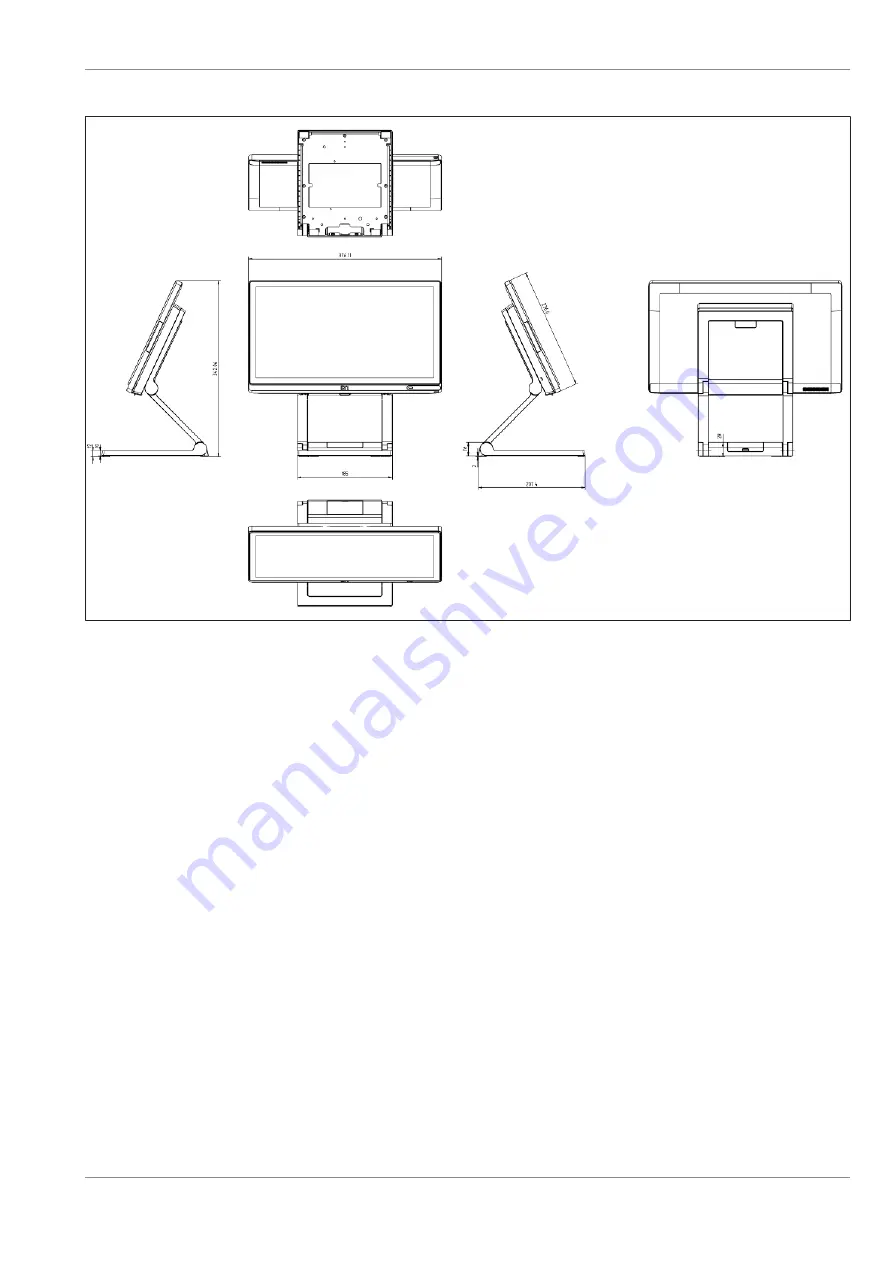
Page 23: ...Please refer to the drawings below for dimensions of the desktop and wall mount versions All dimen sions are specified in millimetres The views of the systems are not drawn to scale 8 2 8 2 Desktop v...
Page 24: ...Planning the Installation 15 6 inch display Copyright 2021 Diebold Nixdorf 01750342843C 8 2...
Page 25: ...Planning the Installation 8 2 1 2 8 2 1 2 Coffee Lake R3 R4 motherboard 15 inch display Copyright 2021 Diebold Nixdorf 01750342843C 8 3...
Page 26: ...Planning the Installation 15 6 inch display Copyright 2021 Diebold Nixdorf 01750342843C 8 4...
Page 27: ...Planning the Installation 8 2 2 8 2 2 Wall mount version 8 2 2 1 8 2 2 1 Whiskey Lake Sx motherboard 15 inch display 15 6 inch display Copyright 2021 Diebold Nixdorf 01750342843C 8 5...
Page 28: ...Planning the Installation 8 2 2 2 8 2 2 2 Coffee Lake R3 R4 motherboard 15 inch display 15 6 inch display Copyright 2021 Diebold Nixdorf 01750342843C 8 6...
Page 29: ...stallation 8 3 8 3 Required operation space WARNING Maintain at least 50 mm from the side of the system to ensure proper ventilation during the operation of the system Copyright 2021 Diebold Nixdorf 0...
Page 30: ...walkway ar eas hallways areas or crowded areas are not recommended Make sure that all applicable building and electric codes and accessibility requirements are followed The mounting area must have ade...
Page 31: ...alling system to the stand standard 9 1 1 9 1 1 Preparing the stand 1 1 Remove the VESA cover by sliding it down wards indicated by arrow NOTE Observe the safety precaution mentioned on the next page...
Page 32: ...face down on the protection sheet 3 Remove the 4 screws 1 that come with the Beetle A Series 9 1 3 9 1 3 Installing system to the stand 1 Fit the system on the stand while holding it in place 1 1 1 1...
Page 33: ...back to access the connector panel at the bottom of the system display 1 4 Remove the cable cover 1 NOTE Left Whiskey Lake Sx motherboard system Left bottom Coffee Lake R3 R4 motherboard system Copyri...
Page 34: ...iskey Lake Sx motherboard system Left bottom Coffee Lake R3 R4 motherboard system 1 7 Tilt the system back to its operating position 8 Replace the VESA cover 1 by pushing it upwards NOTE When uninstal...
Page 35: ...pulling it up from the back 2 Remove the VESA cover by sliding it down wards indicated by arrow NOTE Observe the safety precaution mentioned on the next page when you remove the back cover of stand W...
Page 36: ...tection sheet 3 Remove the 4 screws 1 that come with the Beetle A Series 9 2 3 9 2 3 Installing system to the stand NOTE When installing the system to a stand with I O Hub install the I O Hub before i...
Page 37: ...the I O Hub with the 2 M3x4 screws provided at the positions indicated 1 1 3 Connect the USB C cable to the port indi cated 1 4 Then fit the system on the stand while hold ing it in place Copyright 2...
Page 38: ...en the 4 M4x6 countersunk screws 1 that came with the stand to secure the sys tem to the stand 6 Tilt the system back to access the connector panel at the bottom of the system display Copyright 2021 D...
Page 39: ...Installation to a stand 1 7 Remove the cable cover 1 NOTE Left Whiskey Lake Sx motherboard system Left bottom Coffee Lake R3 R4 motherboard system Copyright 2021 Diebold Nixdorf 01750342843C 9 9...
Page 40: ...1 9 Replace the cable cover NOTE Left Whiskey Lake Sx motherboard system Left bottom Coffee Lake R3 R4 motherboard system 1 10 Tilt the system back to its operating position 11 Replace the VESA cover...
Page 41: ...hen uninstalling the stand always make sure that all cables are disconnected 9 3 9 3 Installing system to the stand with cable covers 9 3 1 9 3 1 Preparing the stand 1 Remove the back cable cover 1 by...
Page 42: ...it down wards indicated by arrow NOTE Observe the safety precaution mentioned on the next page when you remove the back cover of stand WARNING To avoid damage to the back cover of the stand be careful...
Page 43: ...ace down on the protection sheet 3 Remove the 4 screws 1 that come with the Beetle A Series 9 3 3 9 3 3 Installing system to the stand 1 Fit the system on the stand while holding it in place 1 1 1 1 2...
Page 44: ...bottom of the system display 4 Remove the cable cover 1 at the bottom of the system display 1 5 Plug the USB C cable into the port indicated 1 NOTE Left Whiskey Lake Sx motherboard system Left bottom...
Page 45: ...the path as illustrated see arrows 7 Replace the cable cover previously removed NOTE Left Whiskey Lake Sx motherboard system Left bottom Coffee Lake R3 R4 motherboard system 8 Tilt the system back to...
Page 46: ...s NOTE The arrow paths are for illustration pur pose only and are not meant to be ex haustive 10 Replace the VESA cover by sliding it up wards 11 Align the back cable cover 1 with the front cable cove...
Page 47: ...50 powered COM port 5V 12V 4 COM2 RJ50 powered COM port 5V 12V 5 USB3 4 USB 2 0 Type A 6 USB5 6 USB 3 0 Type A 7 24V IN Connection to power 24V DC Input 8 USB1 USB 3 0 Type C with DP and PD 5 24V Powe...
Page 48: ...2 0 Type A 4 USB4 USB 2 0 Type A 5 USB5 USB 2 0 Type A 6 CASH RJ12 Cash drawer 7 24V IN Connection to power 24V DC Input 8 USB1 USB 3 0 Type C with DP and PD 5 24V Power source sink function 9 USB6 U...
Page 49: ...Connector Panel NOTE Maximum 40W load is allowed for any combination of the interface connectors Copyright 2021 Diebold Nixdorf 01750342843C 10 3...
Page 50: ...1 Tilt the display to the back and remove the cable connection cover 1 to uncover the connector panel Whiskey Lake Sx motherboard 2 Connect the cables to their assigned ports 3 Re attach the cable co...
Page 51: ...1 With MINI DIN plugs Diebold Nixdorf key boards the plug remains inserted until re leased 2 Pull the plastic covering from the connecting socket with your thumb The lock is released The metal of the...
Page 52: ...Connector Panel Figure 10 6 RJ45 RJ50 plug 7 To release a RJ45 RJ50 plug push down the latch see arrow Copyright 2021 Diebold Nixdorf 01750342843C 10 6...
Page 53: ...in access to the components on the Coffee Lake R3 R4 motherboard 11 1 11 1 Removing the fan 1 Remove the 2 screws 1 to remove the fan 11 2 11 2 Installing the fan NOTE Install it by following the same...
Page 54: ...2 1 Removing the cable connection cover 2 Remove the display from the stand and lay it on a flat surface 3 Remove the cable connection cover at posi tion 1 by pulling it downwards see arrow to uncover...
Page 55: ...ay not be present depending on your system config uration 8 The SSD can now be removed from their slots by pulling downwards in the direction indicated arrow 1 2 Figure 12 5 Inserting a new SSD 9 Inse...
Page 56: ...ng the step below Figure 12 6 Replacing the RAM 3 To unhook the RAM locate the 2 latches 1 and 2 by their sides 4 Press them in an outwards direction indi cated by the arrows 5 The RAM is now unhooked...
Page 57: ...nwards see arrow to uncover the connector panel 4 Detach all connectors from the connector panel Figure 12 8 Releasing the back cover 5 Lift up and turn the 2 knobs 1 counter clockwise to release the...
Page 58: ...ay not be present depending on your system config uration 8 The SSD can now be removed from their slots by pulling downwards in the direction indicated arrow Figure 12 11 Inserting a new SSD 9 Insert...
Page 59: ...ng the step below Figure 12 12 Replacing the RAM 3 To unhook the RAM locate the 2 latches 1 and 2 by their sides 4 Press them in an outwards direction indi cated by the arrows 5 The RAM is now unhooke...
Page 60: ...included in the wall mount kit The recommended fastener types to wall mount the sys tem are Fischer universal plug UX 6 x 50 http www fischer de Recommended Screw for wall is Pan head self tapping M5...
Page 61: ...commended that the highest point of the display should not exceed 1370mm height It is also recommended that the system is approximately 122cm 48 in from the floor to the centre of the display when the...
Page 62: ...e installed by a professional and qualified installer who is fa miliar with the building construction methods and the electrical code that are govern by the local laws on the public access areas Use o...
Page 63: ...prevent the system from falling and damaged Failing to do so may also cause injury to others Use the recommended fasteners not supplied to attach the wall mount back plate onto the concrete wall Check...
Page 64: ...the system Align the 4 mounting holes of the wall mount front plate onto the mounting holes at the back of the display Secure the wall mount front plate onto the display using the M4 screws provided...
Page 65: ...late that has been mounted on the wall Ensure that the hooks at both sides of the wall mount back plate are se curely locked on the slots of the wall mount front plate Tighten the thumb screw on the t...
Page 66: ...ge angle the angle from normal for A1150 needs to be kept at a maximum of 35 to maintain stability when the D1101 is mounted 14 1 14 1 Installing the D1101 using an adapter kit 1 Remove the VESA cover...
Page 67: ...nting a Second Display A1150 D1101 3 Remove the cable cover 1 from the system 4 Remove the 4 VESA screws 1 from the D1101 5 Then remove the cable cover 2 Copyright 2021 Diebold Nixdorf 01750342843C 14...
Page 68: ...cond Display A1150 D1101 6 Connect the USB C cable to the D1101 7 Replace the cable cover 1 8 Allow the cable to exit from the top opening of the cable cover arrows Copyright 2021 Diebold Nixdorf 0175...
Page 69: ...Mounting a Second Display A1150 D1101 9 Loosen the 2 screws 1 to separate the D1101 adapter The components of the adapter kit are as seen Copyright 2021 Diebold Nixdorf 01750342843C 14 4...
Page 70: ...e D1101 using the 4 countersunk VESA screws 1 provided in the adapter kit 11 Route the cable along the path indicated by the arrows 12 At the stand side remove the 2 VESA screws securing the main syst...
Page 71: ...ounting a Second Display A1150 D1101 13 Slot in the adapter upwards arrow 14 Replace the 2 VESA screws 1 15 Slot in the D1101 and tighten the 2 screws 1 Copyright 2021 Diebold Nixdorf 01750342843C 14...
Page 72: ...Mounting a Second Display A1150 D1101 16 Route the cable along the opening 1 17 Connect the USB C to the port indicated 1 Copyright 2021 Diebold Nixdorf 01750342843C 14 7...
Page 73: ...Mounting a Second Display A1150 D1101 18 Route the cable along the path indicated by the arrows 19 Replace the cable cover 1 on the system Copyright 2021 Diebold Nixdorf 01750342843C 14 8...
Page 74: ...Mounting a Second Display A1150 D1101 20 Replace the VESA cover 1 The D1101 as a second display is assembled Copyright 2021 Diebold Nixdorf 01750342843C 14 9...
Page 75: ...the probe and transmits the data by an electrical USB interface The readout of the data may be integrated easily in a software application NOTE For guide on software application programming please ref...
Page 76: ...k side cover 2 Gently remove the Waiter Lock side cover by prying the 2 ends outwards see arrows with a small screwdriver Figure 15 3 Sliding out the side cover 3 Then slide the side cover out see arr...
Page 77: ...nnection cover 4 Remove either side attach peripheral con nection cover of the Beetle A Series Figure 15 5 Side attach peripheral connection cover re moved 5 The side attach peripheral connection cove...
Page 78: ...aiter Lock module into its respective groove on the system as indicated 1 2 Figure 15 7 Tightening the Waiter Lock screws 8 Then put on and tighten two M3x4 screws at 1 and 2 Figure 15 8 Waiter Lock i...
Page 79: ...Peripherals optional Figure 15 9 Front view with Waiter Lock 12 The front view of the Beetle A Series with the Waiter Lock as seen Copyright 2021 Diebold Nixdorf 01750342843C 15 5...
Page 80: ...r folded in any way Swipe cards should not be allowed to come into close contact with a magnetic field Swipe cards should only be inserted in the top of the specially designed slit of the reading devi...
Page 81: ...igure 15 13 Fitting the MSR module into the Beetle A Series 4 Insert the MSR module into the now exposed USB port of the Beetle A Series 5 Fit each knob on the MSR module into its re spective groove o...
Page 82: ...connection cover 8 Re attach the MSR module side cover 9 The MSR is now installed Back view of the Beetle A Series with the MSR as seen Figure 15 16 Front view with MSR module 10 The front view of the...
Page 83: ...the probe and transmits the data by an electrical USB interface The readout of the data may be integrated easily in a software application NOTE For guide on software application programming please re...
Page 84: ...odule side cover 2 Gently remove the NFC Module side cover by prying the 2 ends outwards arrows with a small screwdriver Figure 15 19 Sliding out the side cover 3 Then slide the side cover out see arr...
Page 85: ...nec tion cover 4 Remove either side attach peripheral con nection cover of the Beetle A Series Figure 15 21 Side attach peripheral connection cover re moved 5 The side attach peripheral connection cov...
Page 86: ...e into the now exposed USB port of the Beetle A Series 7 Fit each knob on the NFC Module into its re spective groove on the system as indicated 1 2 Figure 15 23 Tightening the screws of the NFC module...
Page 87: ...side attach peripheral connec tion cover 10 Re attach the NFC Module side cover 11 The NFC Module is now installed Figure 15 25 Front view with NFC module The front view of the Beetle A Series with th...
Page 88: ...1 1 Remove the I O Hub cover by pulling it up from the back 1 Figure 15 26 Disconnecting connectors from the I O Hub 2 Disconnect the USB C cable from the port indicated 1 3 Disconnect all other conne...
Page 89: ...he I O Hub 4 Remove the 2 M3x4 screws at the positions indicated 1 5 The I O Hub can now be removed 15 4 2 15 4 2 Installation of I O Hub NOTE Install it by following the same steps in reverse order C...
Page 90: ...tallation only requires attaching the module to the system by tightening two screws The module can be rotated 165 degrees clockwise and 165 degrees anti clockwise WARNING Do not stare into the red LED...
Page 91: ...ation Figure 15 31 BCR module The BCR module is as shown Figure 15 32 Removing the BCR top cover 1 Remove the BCR top cover by inserting a small flat head screwdriver into the slot 1 and pry open gent...
Page 92: ...w Figure 15 34 Removing the peripheral connection cover 4 To attach the BCR module remove the pe ripheral connection cover 1 on the Beetle A Series Figure 15 35 Docking the BCR to the system 5 Dock th...
Page 93: ...ivelling the BCR Scanner 6 Swivel the Scanner such that the 2 locking screws are accessible Figure 15 37 Tightening the locking screws 7 Tighten the 2 locking screws 1 with a screwdriver Copyright 202...
Page 94: ...top cover 8 Snap back the BCR top cover in the direction indicated by the arrow 9 The BCR module installation to the Beetle A Series is now complete 15 5 3 15 5 3 Swivel angle Figure 15 39 BCR swivel...
Page 95: ...ctive of processor type on the monitor DN ID xx xx Date xx xx is the placeholder of the BIOS version number Following the completion of the BIOS boot up the BIOS will attempt to boot up an operating s...
Page 96: ...lty 6 Ambient Light Sensor Proximity Sensor not present or faulty Cable loose or Capacitive sense board may be faulty 7 PCH Hot was activated Excessive load or thermal pads may be degraded 8 Processor...
Page 97: ...size or memory modules do not match 0x53 Memory initialization error No usable memory detected 0x54 Unspecified memory initialization error 0x55 Memory not installed 0x56 Invalid CPU type or Speed 0x...
Page 98: ...egacy Option ROM 0xD6 No Console Output Devices are found 0xD7 No Console Input Devices are found 0xD8 Invalid password 0xD9 Error loading Boot Option LoadImage returned error 0xDA Boot Option is fail...
Page 99: ...Climatic Class DIN IEC 721 3 3 Class 3K3 up to 40 C Operating Temperature 5 C to 40 C Humidity 5 to 85 Relative humidity 1g m3 to 25g m3 Condensation is not permitted Display Characteristics Pixels H...
Page 100: ...80 socket for SSD 1x M 2 2230 socket for WiFi External MSR Waiter Lock NFC reader Other Features Projected capacitive touch panel Ambient Light Sensor Proximity Sensor Hardware TPM 2 0 optional Integr...
Page 101: ...N IEC 721 3 3 Class 3K3 up to 40 C Operating Temperature 5 C to 40 C Humidity 5 to 85 Relative humidity 1g m3 to 25g m3 Condensation is not permitted Display Characteristics Pixels H x V 1024 x 768 19...
Page 102: ...ocket for WiFi External MSR Waiter Lock NFC reader 2D Barcode Reader Other Features Projected capacitive touch panel Ambient Light Sensor Proximity Sensor Hardware TPM 2 0 optional Integrated antenna...
Page 103: ...y the power adapter and power cord that has obtained CCC certification and meets the certification standards Rated input voltage 100 240VAC Rated input current 2 0A Input frequency range 47 63 Hz Rate...
Page 104: ...ght Sony Felica NXP DESfire NXP SmartMX with JCOP RF Operating Frequency 13 56 MHz Host Interface USB 2 0 full speed CCID protocol support Rated Voltage 5 V Rated Current 300mA on transmitter path RF...
Page 105: ...DFP Source only 5V 12V 2A PUSB12V Powered USB 12V 3A PUSB24V Powered USB 24V 3A USB1 USB2 USB 3 0 Type A COM5 6 7 RJ50 Powered COM ports 5V 1A combined 12V 1A combined LAN RJ45 Gigabit LAN Cash RJ12...
Page 106: ...Technical Data Figure 19 1 I O Hub front view Figure 19 2 I O Hub back view Copyright 2021 Diebold Nixdorf 01750342843C 19 8...
Page 107: ...Technical Data 19 3 1 19 3 1 Block Diagram Figure 19 3 Block diagram of I O Hub Copyright 2021 Diebold Nixdorf 01750342843C 19 9...
Page 108: ...epends on the power adapter used See above table for the applicable to tal power available USB 2 0 USB3 5V 0 5A USB4 5V 0 5A USB5 5V 0 5A USB Type C USB2 5V 3A 12V 3A USB1 5V 3A 12V 3A 24V 4A Powered...
Page 109: ...rf 2 TH210 series Diebold Nixdorf 3 TH230 series Diebold Nixdorf 4 TH250 series Diebold Nixdorf 5 TH320 series Diebold Nixdorf 6 P1200 series Diebold Nixdorf WARNING Connecting printer that are not in...
Page 110: ...splay LED Light Emitting Diode LVDS Low Voltage Differential Signal MSR Magnetic Stripe card Reader ODD Optical Disk Drive OSD On Screen Display POS Point Of Sales SSD Solid State Drive SVGA Super Vid...
Page 111: ...DIEBOLD NIXDORF 5995 Mayfair Road North Canton OH 44720 United States 2019 Diebold Nixdorf Incorporated All Rights Reserved...