Dickey-John Flex4 Operator'S Manual Download Page 53

OPERATOR’S  MANUAL 


NOTE:  The Enter button will not select 

a text field. 

LABEL ENTRIES 

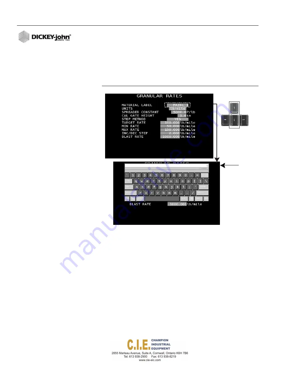
1.  To create label names, such as a Material Name, highlight the field and 

begin typing the name. A virtual keyboard displays onscreen and the 
name as entered appears at top of the virtual keyboard. 

2. Press the 

Enter 

button to accept the label entry. 


Figure 49 


Virtual Keyboard 


Using


the


keyboard


up/down


arrow


buttons


select


and


highlight


a


parameter


Material


Label


50 / FLEX4 PROTM PROGRAMMING 

Flex4 Pro

TM 

Control System 

6010541 Rev A 

Summary of Contents for Flex4

Page 1: ...FLEX4 PRO PUBLIC WORKS CONTROL SYSTEM Operator s Manual SINCE 1966 FLEX PRO...

Page 2: ...Display settings Camera Display Alarms 29 Operation 31 Pre operating checklist 32 Spreading material 32 Blast 33 Pause 34 Material selection 35 Unload material 36 Manual ground speed override 38 Auto...

Page 3: ...pinner system response calibrations f6 103 Recording calibration data 104 Maintaining calibration accuracy 105 Granular drop test calibration 106 Liquid drop test calibration F6 109 Auxiliary system r...

Page 4: ...ich if not avoided could result in death or serious injury Use of the word CAUTION with the Safety Alert Symbol indicates a potentially hazardous situation which if not avoided may result in minor or...

Page 5: ...OPERATOR S MANUAL Flex4 ProTM Control System 6010541 Rev A SAFETY NOTICES 2...

Page 6: ...truck stops The operator interface consists of a Flex4 ProTM Tablet Operator Switch Module Desired material application rates are entered on the Setup screens by attaching a keyboard Figure 1e Flex4 P...

Page 7: ...OPERATOR S MANUAL 4 INTRODUCTION Flex4 ProTM Control System 6010541 Rev A...

Page 8: ...power controller ECU USB port hub USB CAN adapter DC DC converter Optional components 10 CAN extension harness Output module and harness Solenoid driver Electric motor pump driver Camera 4 3mm lens C...

Page 9: ...C to 49 degrees C Storage Temperature 22 degrees F to 160 degrees F 30 degrees C to 71 degrees C Humidity 5 95 non condensing The Flex4 ProTM tablet should not be turned on until product temperature s...

Page 10: ...ions on the Flex4 ProTM tablet are used 1 Tablet power cable 2 USB port connects to Tough Hub Figure 3 Flex4 ProTM Tablet Connections volume adjustment power button Stylus Flex4 ProTM Control System 6...

Page 11: ...Pause button stops applying material but continues to calculate the total miles driven Auto mode must be active for the Pause feature to operate BLAST The Blast button applies material at a pre progr...

Page 12: ...ation files to program each tabletand master control module with system calibration values Figure 5 USB Data Port Connection RATE CONTROL MODULE The Rate Control Module houses the system s primary int...

Page 13: ...Do not install the module in any orientation other than shown in Figure 7 The connection wires must not be mounted upward as moisture can collect inside the unit and damage the circuits 4 Mount with...

Page 14: ...control loop and connect the devices to their respective inputs on the harness making certain to match PWM 1 Servo 1 with FB1 PWM2 Servo 2 with FB2 etc 7 Secure any unused and excess cable lengths whe...

Page 15: ...s do not face upward 3 Mount with the label side of the module facing out 4 To bolt the member to a frame Use the enclosure as a template to mark the location ofthe mounting holes Drill two 9 32 inch...

Page 16: ...TENING VICE 1 4 SPLIT LOCKWASHER 5 To tie strap the module to a frame Use one long tie strap to loop around the member bodyand through both mounting holes as illustrated in Figure 9 If necessary dril...

Page 17: ...shutoff outputs 9 Route wires in locations where they will not be damaged 10 Secure the harness with tie straps NOTE The last module harness in the system must have a CAN terminator installed for prop...

Page 18: ...MISCELLANEOUS COMPONENTS RAM TOUGH HUB USB distribution point for the system Provides connections to the USB CAN adapter camera adapter and the USB data port below the Operator Switch Module USB CAN...

Page 19: ...down pressure applied on the underbody scraper FLOW METERS Flow meter measures the flow rate of material being applied VALVE CONTROL OUTPUT Flex4 rate controllers control PWM hydraulic and Servo valve...

Page 20: ...1 Remove the 4 screws from the back of the tabletplate 2 Align switch module bracket holes with the plate holes 3 Secure the bracket and plate with the 4 screws Attach Switch Module to Operator Switc...

Page 21: ...k Cab 1 Secure bracket to truck cab using 4 SAE screws included 2 Insert ball mount into bracket assembly and tighten wingnut 3 Adjust tablet for ideal viewing by loosening tightening the wingnut 18 I...

Page 22: ...rter and the USB CAN adapter This plate should be mounted near the PCECU module Recommended mounting location is inside the cab on the floor back of cab wall or center console The Accessory Plate shou...

Page 23: ...ric Motor Pump Driver and Optional Output Module Harness power adaptor Camera to Adaptor USB cable Powerconnection to Video Camera CAN Terminator Switch Module 466495210 RAM Tough Hub USB Can Adaptor...

Page 24: ...PC ECU Rate Control Module 467985410S1 Rate Control Module Harness 466495071 Connects to RateControl Electric Motor Extension Harness 466495060 Module Harness Pump Driver 466495430 Harness Applicatio...

Page 25: ...on layout RAM Tough HUB Connections mini USB connection Spade connection Connect to tablet using barrel jack connector and then plug USB male into cable coming out of the DC DC adapter female USB 6 Co...

Page 26: ...ule Cab or Terminator Electric Pump Extension Driver Harness Harness PWM Ch 4 Aux S Spinner PWM Ch 3 Granular PWM Ch 2 Auxiliary PWM Ch 1 Liquid CH4 Spinner Feedback CH1 Liquid Feedback CH2 Auxiliary...

Page 27: ...identify what function is connected to the analog 1 2 3 or 4 connector Figure 20 RoadWatch Temperature adapter and Flex4 Interface Cable Connects to RateControl Module Harness via Analog 1 2 3 or 4 c...

Page 28: ...arness if used Figure 22 Output Module Harness Output Module Rate Control Module Harness or Extension Harness Electric Motor Pump Driver Harness Boom Shutoff Valves Output 1 Output 2 Output 3 Output 4...

Page 29: ...OPERATOR S MANUAL 26 INSTALLATION Flex4 ProTM Control System 6010541 Rev A...

Page 30: ...ons and operation functions that include 1 Control channel application rate windows displays up to 4channels when assigned as materials nonspinner 2 Display function buttons on left and right side ofd...

Page 31: ...ain Channel must be selected using spread width knob 2 DISPLAY FUNCTION BUTTONS Twelve buttons are located on the left and right side of the tabletuser interface screen providing screen navigation and...

Page 32: ...settings appearance of the camera window display onthe tablet Display brightness lightness darkness ofscreen Alarm volume high low adjustment of audible alarm whenerror occurs To change a Display Set...

Page 33: ...25 Display Settings Screen 11 DAY AND NIGHT MODE Day and Night mode adjusts the tablet screen colors for better visibility to sunlight or while operating at night The default screen setting is night m...

Page 34: ...rms self tests including system configuration and application data during startup If an error occurs at power up or during operation an error message displays with recovery information IMPORTANT The s...

Page 35: ...ox until the channel and spread width boxes shift position Figure 28 Repositioning Channel and Spread Width SPREADING MATERIAL To Begin Spreading Material 1 Press the Auto On Off button to engage Auto...

Page 36: ...icle conditions to increase the amount of material spread by a predefined rate Blast can be used in Auto mode manual control channel override and manual ground speed To Activate Blast 1 Press the Blas...

Page 37: ...dspeed To activate Pause 1 To enable press the Pause button An alarm sounds indicatingPause is activated and Pause will appear on thedisplay 2 To disable press the Pause button again An alarm sounds i...

Page 38: ...and ground speed at 0 press theMaterial Select button 2 At the Material Selection screen press either the Granular orthe Liquid button 3 Press the Select Arrow button to choose the desiredmaterial Sel...

Page 39: ...nular channel will stay active 3 Press the CH ON button to re activate thechannel Figure 33 Turning a Channel Off CH OFF ROUTE SELECT SPINNER ANTI ICE UNLOAD MATERIAL The Unload feature quickly remove...

Page 40: ...OPERATOR S MANUAL Figure 34 Unloading a Material Ensure the area is clear prior to unloading to avoid possible injury Flex4 ProTM Control System 6010541 Rev A OPERATION 37 START X X STOP...

Page 41: ...ed button until EnableManual Speed is highlighted 3 Press the Select Arrow buttons to increase decrease manualspeed Figure 35 Manual Override Increase decrease manual speed 4 Press the Back button to...

Page 42: ...verts to automatic manual override and continues to operate the control channel in a manual override state Manual override allows material to be spread at the same programmed rate without interruption...

Page 43: ...incorrect passcode entry 3 Press the Enter button to accept the passcode and displaythe Operate screen Figure 38 Driver Login Screen To Logout 1 At the Operate screen press the Logout button The driv...

Page 44: ...hen pressed To enable Boom Section Control Press the Section ON button s to turn on When a section is turned on the button changes to a Section OFF button Each section can be turned on and off indepen...

Page 45: ...annels are ON Anti Ice OFF Granular and Liquid channels are OFF Anti Ice ON ACCESSORY SENSORS A dedicated accessory window at screen bottom of the Operate screen displays the enabled accessory sensors...

Page 46: ...ecreases If gate height is decreased the conveyor speedincreases Figure 43 Gate Increase Decrease Buttons Left Right Spinner Left Right Spinner button toggles between activating the left spinner right...

Page 47: ...een provides accumulated material usage miles and hours driven using Auto mode Blast and Pause functions Total operating data can be viewed in current run totals season run totals or by route NOTE Tot...

Page 48: ...material 4 To reset totals press the Reset Current Material button 5 Reset Trip Log button clears accumulated miles to zero 6 Route Select button toggles and displays totals for eachroute 7 Back butt...

Page 49: ...OPERATOR S MANUAL 46 OPERATION Flex4 ProTM Control System 6010541 Rev A...

Page 50: ...keys include F1 Operate screen F2 Granular Channel Setup F3 Liquid Channel Setup F4 Auxiliary S Granular Liquid Spinner ChannelSetup F5 Auxiliary Granular Liquid Channel Setup F6 Calibration F7 Diagn...

Page 51: ...Attach the keyboard to the USB port below the Operator Switch Module KEYBOARD FUNCTIONS 1 Function labels identify each function button 2 Function button displays menus for respective functions 3 Numb...

Page 52: ...OPERATOR S MANUAL Figure 48 Open a Text Window Press Enter to open text window Flex4 ProTM Control System 6010541 Rev A FLEX4 PROTM PROGRAMMING 49...

Page 53: ...begin typing the name A virtual keyboard displays onscreen and the name as entered appears at top of the virtualkeyboard 2 Press the Enter button to accept the label entry Figure 49 Virtual Keyboard U...

Page 54: ...ping numbers from the keyboard A virtual keypad display onscreen and the number as entered appears at top of the virtualkeypad 2 Press the Enter button to accept the label entry Figure 50 Virtual Keyp...

Page 55: ...OPERATOR S MANUAL 52 FLEX4 PROTM PROGRAMMING Flex4 ProTM Control System 6010541 Rev A...

Page 56: ...gging F12 IMPORTANT System programming MUST be conducted before performing a system calibration Accurate system calibration constants are determined through regular calibration routines Known constant...

Page 57: ...verify the granular channelis enabled 2 Press the F3 Liquid button and set the channel toprewet 3 Press the F5 Auxiliary button and set the channel toAnti Ice 4 Press the F1 Operate button the Anti Ic...

Page 58: ...Method Step or Rate Blast Rate The channel s current status displays as Enabled or Disabled To Change the Channel s Status 1 Use the Up or Down arrow keys on the keyboard to select and highlight the...

Page 59: ...bration should be performed CALIBRATION GATE HEIGHT Calibration Gate Height displays only if the gate height sensor is enabled at the Accessory Sensor screen F9 If enabled the calibration gate height...

Page 60: ...r this channel Minimum rate establishes the minimum application rate that the control allows Target rate cannot be decremented to a value lower than this established Min Rate 5 Enter a maximum applica...

Page 61: ...is Rate 1 Other rates are selected by pressing the Rate Increase Decrease button on the switch module 4 Enter a desired blast rate that applies a higher than normal spot application when the Blast but...

Page 62: ...Feedback 3 Press the Enter key to confirm the selection 4 Use the keyboard arrow keys to scroll to each constant s selection box Figure 55 Granular Configuration Screen CONTROL MODE MANUAL WITH FEEDBA...

Page 63: ...e granular control channel on each particular spreader vehicle VALVE BOOST Increases the amount of system response initially applied to the granular control to reach final operating speed as quickly a...

Page 64: ...splays if enabled as an accessory sensor at the F9 Accessory Sensor screen This value is viewable only and indicates the current setting The value automatically adjusts when a granular calibration is...

Page 65: ...l Label Units K Factor Application Rate Method Step or Rate Blast Rate The channel s current status is displayed as Enabled or Disabled To Change the Channel s Status Function 1 Use the Up or Down Arr...

Page 66: ...rameters Figure 57 Liquid Application Flex4 ProTM Control System 6010541 Rev A SYSTEM PROGRAMMING 63 20 6 0 825 42 1 0 825 57 8 LIQ 1 gal ac gal ac gal ac gal ac gal ac gal ac ANTI ICE RATES A ICE 1 g...

Page 67: ...during the liquid calibration APPLICATION RATE METHOD Two methods are available to control the application of material STEP Method Rate Method STEP Method STEP Method allows rates to be changed by a...

Page 68: ...ow Target rate cannot be decremented to a value lower than this established minimum and maximum rates INC DEC STEP The increment decrement rate establishes the amount of change of the entered target r...

Page 69: ...rolling or monitoring boom sections and assigns boom sections to a liquid or auxiliary channel A total of 6 boom sections can be controlled by the system A DICKEY john output module must be installed...

Page 70: ...oom sections are controlled by a DICKEY john output module allowing sections to be turned on and off at the Operate screen with assigned section buttons Sense Boom sections are controlled by a separat...

Page 71: ...Refer to Assign Auxiliary S as Spinner to configure channel for spinner control Press the Calibration F6 key to initiate channel calibration Figure 61 Aux S Screen ASSIGN AUXILIARY S AS SPINNER Spinn...

Page 72: ...UENCY Drive Frequency specifies the frequency for the installed proportional valve The recommended setting for this option should be specified from the valve manufacturer NO GROUND SPEED Select Yes to...

Page 73: ...ach final operating speed as quickly as possible AFILT Filters the feedback signal to minimize the effect of electrical noise and mechanical vibrations The smaller the number the greater degree of fil...

Page 74: ...as channels one and two Four materials are possible and assigned as materials 5 8 Configuration and boom setup for an auxiliary channel must be enabled at this screen for the channel to be in an activ...

Page 75: ...ion can be viewed on the Operate screen when enabled at this screen To enable Accessory Sensors 1 At the F9 Accessory menu screen highlight the Analog AccSensor input box and press the Enter key to op...

Page 76: ...ition 4 Measure the height at the closed position and enter that amountin inches cm in the Closed input field 5 Press C to capture the current gate height voltage at the closed setting The voltage aut...

Page 77: ...es at the Temperature Enabled input box 3 Enter the alarm temperature in degrees F to alert of road temperature changes to indicate when application rate or material changes are required Temperatures...

Page 78: ...the main harness for successful calibration If the interface cable and the DICKEY john temperature sensor adapter is disconnected when the calibration is performed an error screen displays NOTE Road W...

Page 79: ...Temperature section for display appearance on Operate screen To enable Air Temperature Sensor Values 1 Air temperature sensor input values and calibration proceduresare similar to road temperature se...

Page 80: ...tagereading IMPORTANT It is recommended that voltages are automatically captured but manual entry of voltages can be entered 7 Enter a tank level alarm percentage to warn when thetank level has reache...

Page 81: ...ress C to capture the minimum pressurereading 5 Highlight the maximum pressure input box 6 Position the scraper downward until road contact occurs and the desired normal road contact pressure is reach...

Page 82: ...as BED 113 To enable a Bed Height Sensor 1 At the Bed Height Menu screen select Yes at the Bed HeightEnabled input box 2 Highlight the Bed Down input box The dump bed must be completely down and the s...

Page 83: ...nd 5 Enter an appropriate active and inactive label that identifies the sensor type and status on the Operate screen 6 Select the Alarm Mode as either Never Auto or Always Figure 72 Digital Accessory...

Page 84: ...hen the system is active and controlling ALWAYS Alarm occurs after the defined alarm delay during operate mode and shutdown mode ALARM DELAY Amount of time delay in seconds that occurs before an alarm...

Page 85: ...OW ALARM LIMIT Frequency The High and Low Alarm limit values determine when an alarm is triggered to warn when a certain condition is met that is set by user defined parameters ALARM DELAY Amount of t...

Page 86: ...ppears on Operate screen as SCRAPER To create Joystick Control Names 1 At the F9 Accessory menu screen press 7 on the keyboard to display the Joystick Labels screen 1 Select Yes at the Joystick Sense...

Page 87: ...Troubleshooting GPS Sensor To access the System Setup Screen 1 Press the F10 key to display the System menuscreen 2 At the System Setup screen press the respective item number to open a menu item Figu...

Page 88: ...to zero the screen will show a BLAST but no material falls DATE AND TIME The date and time of the unit is factory set to Central Standard Time The time can be re set to the appropriate time zone by en...

Page 89: ...on future releases Contact Technical Support at 1 800 637 3302 for availablelanguages Units of measurement available US Metric To enter Units and Language 1 At the F10 System menu screen press the 3...

Page 90: ...d identify the system s current software version 1 At the F10 System Menu screen press 4 on the keyboard to select the Service menu screen SOFTWARE VERSION 1 Press 1 at the Service screen to display t...

Page 91: ...ard mode that allows keyboard use when the ground speed is above 0 AND the ground speed is OFF High level users have the ability to change the keyboard menu settings while the master switch state is o...

Page 92: ...modified as any changes could affect performance Contact DICKEY john Technical Support at 1 800 637 3302 for assistance 1 At the F10 System menu screen press 5 on the keyboard todisplay the Troublesho...

Page 93: ...control versusoff When blast and pause function was activated GPS coordinates of location by time and date Log GPS Position per Event This feature must be enabled to log events with GPS position and c...

Page 94: ...from the left and right sideof the truck at the Operate screen 6 Select Yes to control raising and lowering the gate height from the cab 7 Enter the increase decrease PWM that determines how fast the...

Page 95: ...e opens orcloses INC DEC TIME The time entered determines how long the PWM signal is sent to the electric actuated signal each time the gate increase or decrease button is pressed from the Flex4 ProTM...

Page 96: ...ption and may give instructions on how to resolve the issue Each alarm type has an associated alarm number that can be cross referenced in the Troubleshooting and Alarms section Some alarms require a...

Page 97: ...name for a truck which can be changed at anytime A Truck ID is used as part of the file name during import export of configuration and data downloading to correlate the truck with the appropriate data...

Page 98: ...routes and roads with materials spread miles driven and route spread can be recorded for an individual driver The default language is English but a specific language can be chosen so that during logo...

Page 99: ...iate language if available To remove a driver s name and passcode highlight the corresponding delete input box located next to theuser Use the or key to enter a checkmark to select Upon exit of this s...

Page 100: ...e Configuration Setup screen 2 Highlight the Configuration Passcode input box and selectEnabled 3 At the Passcode input box enter a passcode using numbers only A passcode can be enteredat this screen...

Page 101: ...on screen 2 Highlight the Route Name input box and type in the desired name A maximum of 12 digits is accepted To remove a route name highlight the corresponding delete input box located next to the u...

Page 102: ...displays and clears only the current materials displayed on the Operate screen Press More button to view additional materials 4 At the Material menu screen select the corresponding number key to view...

Page 103: ...ATOR S MANUAL NOTE Season totals can only be cleared using the keyboard at the Operational Totals screen Figure 92 Operational Totals Screen 100 SYSTEM PROGRAMMING Flex4 ProTM Control System 6010541 R...

Page 104: ...y in miles and hours for Automatic Blast and Pause modes These totals are informational only and cannot be changed or cleared To view Lifetime Totals 1 At the F12 Data Logging screen press 6 on the ke...

Page 105: ...OPERATOR S MANUAL 102 SYSTEM PROGRAMMING Flex4 ProTM Control System 6010541 Rev A...

Page 106: ...performed Manual fine tuning for optimum performance is acceptable IMPORTANT During calibrations the truck must be running and the RPM s should be within the truck s normal operating range GRANULAR RE...

Page 107: ...asgranular RECORDING CALIBRATION DATA After performing each calibration record the calibration constants on the Calibration Data Record sheets included with this manual If console replacement is nece...

Page 108: ...ponents including hydraulic hoses fluid changes and normal wear A yearly system calibration of all control channels at the beginningof each spreader season SYSTEM RESPONSE ADJUSTMENTS Adjustments afte...

Page 109: ...verify thegate height is adjusted to the proper setting on the V Box spreader If tailgate spreads are in use ensure auger isfull 2 Load enough material to provide a uniform flow throughoutthe calibrat...

Page 110: ...icating the previous spreader constant and the sensor counts accumulated during the current run 7 Perform the next step while the screen waits for theresults 8 If using a vehicle scale reweigh the tru...

Page 111: ...OPERATOR S MANUAL Figure 95 Granular Drop Test Procedure 108 CALIBRATIONS Flex4 ProTM Control System 6010541 Rev A...

Page 112: ...splays the KFactor DROP TEST PREPARATION 1 Load vehicle tank with material 2 Position a suitable container to catch all the material dispensed through the liquid pump The container must be large enoug...

Page 113: ...ed duringthe current run For a pressure based system the previous nozzle constant and collection time display The screen asks for an entry of gallons before proceeding 7 Perform the next step while th...

Page 114: ...d the values can be manually adjusted to improve application accuracy Refer to Appendix A for steps to re calculate a new flow meter constant This constant can be manually entered on the Liquid Config...

Page 115: ...1 At the System Calibration screen F6 select SpinnerSystem Response and follow the onscreen instructions 2 At the Spinner System Response screen press R to begin test 3 Spinner will be set to off when...

Page 116: ...OPERATOR S MANUAL Figure 98 Spinner System Response Screens Flex4 ProTM Control System 6010541 Rev A CALIBRATIONS 113...

Page 117: ...ial 2 At the F6 Calibration menu select Spinner Spread Width andfollow onscreen instructions 3 Position a suitable container to catch all granular materialdispensed from the conveyor auger The larger...

Page 118: ...l calibration a calibration complete screenappears Press D to return to the main Calibrationscreen Figure 100 Spinner Spread Width Enter measured spread width into popup window Flex4 ProTM Control Sys...

Page 119: ...tor harness through an adapter harness MAXIMUM CONTROL SPEED Indicates the allowed maximum speed in AUTO mode before a Maximum Speed Exceeded warning occurs The value entered is based on the highest s...

Page 120: ...tem begins to operate when ground speed sensor pulses start Until this threshold is crossed the startup ground speed signal is used CONTROL SHUTOFF SPEED Minimum ground speed allowed before the system...

Page 121: ...establishes a ground speed constant s for the vehicle The constant is determined by counting the number of ground speed sensor pulses generated in a distance of one mile Figure 102 Ground Speed Calibr...

Page 122: ...e calibration begins as the vehicle is moving 5 Drive at normal operating speed NOTE For better accuracy it is recommended to slow down at the second marker so reaction time is better when pressing S...

Page 123: ...OPERATOR S MANUAL 120 CALIBRATIONS Flex4 ProTM Control System 6010541 Rev A...

Page 124: ...een appears after pressing the Import Export button Enter the passcode and press the Enter button to proceed Figure 103 Passcode Screen NOTE USB memory device must be inserted into the USB port before...

Page 125: ...URATION FILE NAME Flex4_Truck ID_2016 07 29 EXPORT LOG DATA FILES Log data files are exported following the same procedure as exporting configuration files Log data files can be imported to a reportin...

Page 126: ...Import Export button 3 At the Import Export screen select Data USB Export button The Export to USB confirmation screen displays the file name that contains the configuration files 4 Select the type o...

Page 127: ...created that Flex4 data is stored Flex4_DataFolder Each time an export occurs the file name is saved with the Flex4 name identifier the Truck ID date of the download and time of the download FILE STRU...

Page 128: ...Filebutton 5 Select the desired file types to import and press the ImportNow button A Data Import screen indicates file s are loaded Figure 106 Importing Configuration Files Flex4 ProTM Control Syste...

Page 129: ...the Reboot button to turn the system off and on again to accept imported data Figure 107 Rebooting the Tablet 126 IMPORT EXPORT DATA FILES Flex4 ProTM Control System 6010541 Rev A DATA IMPORT DONE YOU...

Page 130: ...press when the image is captured and transferred to a USB memory device The USB memory device must be inserted before a screen capture is possible To Capture Screen Shot 1 Insert USB memory device 2...

Page 131: ...OPERATOR S MANUAL 128 CAPTURE SCREEN SHOT Flex4 ProTM Control System 6010541 Rev A...

Page 132: ...ust be enabled at the appropriate ground speed setting Actual readings will display on the Diagnostics screen at the defined rate and the manual ground speed entered when the switch module Auto On but...

Page 133: ...1 Press the appropriate number on the keyboard to select thePCECU control module or output module screens 2 At the selected Diagnostics screen press the switch module AutoOn Off button to On to displa...

Page 134: ...y or a defective joystick Figure 111 PCECU Diagnostics Screen CONTROL MODULE The Control Module Diagnostics screen provides sensor readings for control channels auxiliary channel spinner and accessory...

Page 135: ...ymaster module Filtered Feedback Filtered Feedback is the actual pulses per second of the feedback sensor and indicates the PWM signal being sent to the hydraulic control valve No filtered feedback co...

Page 136: ...increase until the desired target rate is reached and then should remain steady when achieved Ground Speed Frequency Ground Speed Frequency identifies the pulses per second coming into the control mo...

Page 137: ...ing into the control module and could indicate a potential problem with the module not reading a signal from the sensor or a speed sensor failure Voltage Readings Voltage readings from the truck batte...

Page 138: ...oss conveyors valves and the accessory 12 volt switched output Press the appropriate Accessory button to verify correct position An incorrect state on the screen that doesn t correspond with the physi...

Page 139: ...OPERATOR S MANUAL 136 DIAGNOSTICS Flex4 ProTM Control System 6010541 Rev A...

Page 140: ...TROUBLESHOOTING Error messages display when an abnormal event occurs For any failure that persists contact DICKEY john Technical Support at 1 800 637 3302 Flex4 ProTM Control System 6010541 Rev A TRO...

Page 141: ...larm Communication to the member module was lost but has been re established Verify module is connected properly 2 Inspect CAN harness for damage 3 Inspect ECU harness and fuse fordamage 4 Inspect ECU...

Page 142: ...1 Check calibration numbers andre run calibration 2 or accept default values and continue calibration 302 Invalid Temperature Calibration Temperature calibration did not complete 1 Verify temperature...

Page 143: ...value 1 Adjust alarm setting 2 Check sensor 519 Digital Accessory 2 Low Sensor has reached the defined low alarm limit value 1 Adjust alarm setting 2 Check sensor 520 Digital Accessory 2 Shutdown Digi...

Page 144: ...k battery ground connections and wiring 2 Inspect actuator harness for damage around the PWM and Servo valve connections Repair or replace harness 3 Inspect PWM or Servo valve drivers for damage and r...

Page 145: ...OPERATOR S MANUAL 142 TROUBLESHOOTING Flex4 ProTM Control System 6010541 Rev A...

Page 146: ...R 2 If AUX S is configured as GRANULAR and AUX is configuredas PREWET then AUX rate is linked to AUX S 3 If GRANULAR is set to Enable and AUX is configured as PREWET and AUX S is NOT Granular then AUX...

Page 147: ...GRANULAR ENABLED PWM LIQUID LIQUID ANTI ICE PWM SERVO AUX S SPINNER PWM AUX NOT USED NOT USED Tow Plow 2 Granular 2 Pre Wet GRANULAR ENABLED PWM LIQUID LIQUID PRE WET PWM SERVO AUX S GRANULAR PWM AUX...

Page 148: ...APR is known to be 315 LBS MILE adjust SPR CON using the above formula New SPR CON 100 x 300 95 2 NOTE Keyboard enter the new SPR CON on the appropriate Granular configuration screen Adjusting Liquid...

Page 149: ...EXAMPLE A 360 pulses per revolution for Dj sensor p n 46436 017X B 25 turns of the sensor shaft for each turn of the final shaft C 50 pounds of material discharged per revolution of final shaft SPR CO...

Page 150: ...6010541 Rev A...

Page 151: ...OPERATOR S MANUAL APPENDIX C Flex4 ProTM Control System 6010541 Rev A APPENDIX C 147...

Page 152: ...FLEX4 PRO PUBLIC WORKS CONTROL SYSTEM DICKEY john and the DICKEY john Logo are registered trademarks and Flex4 is a trademark of DICKEY john P N 6010541 Rev A Operator s Manual SINCE 1966...

Reviews: