background image


H

H

H

y

y

y

d

d

d

r

r

r

a

a

a

u

u

u

l

l

l

i

i

i

c

c

c


C

C

C

i

i

i

r

r

r

c

c

c

u

u

u

i

i

i

t

t

t


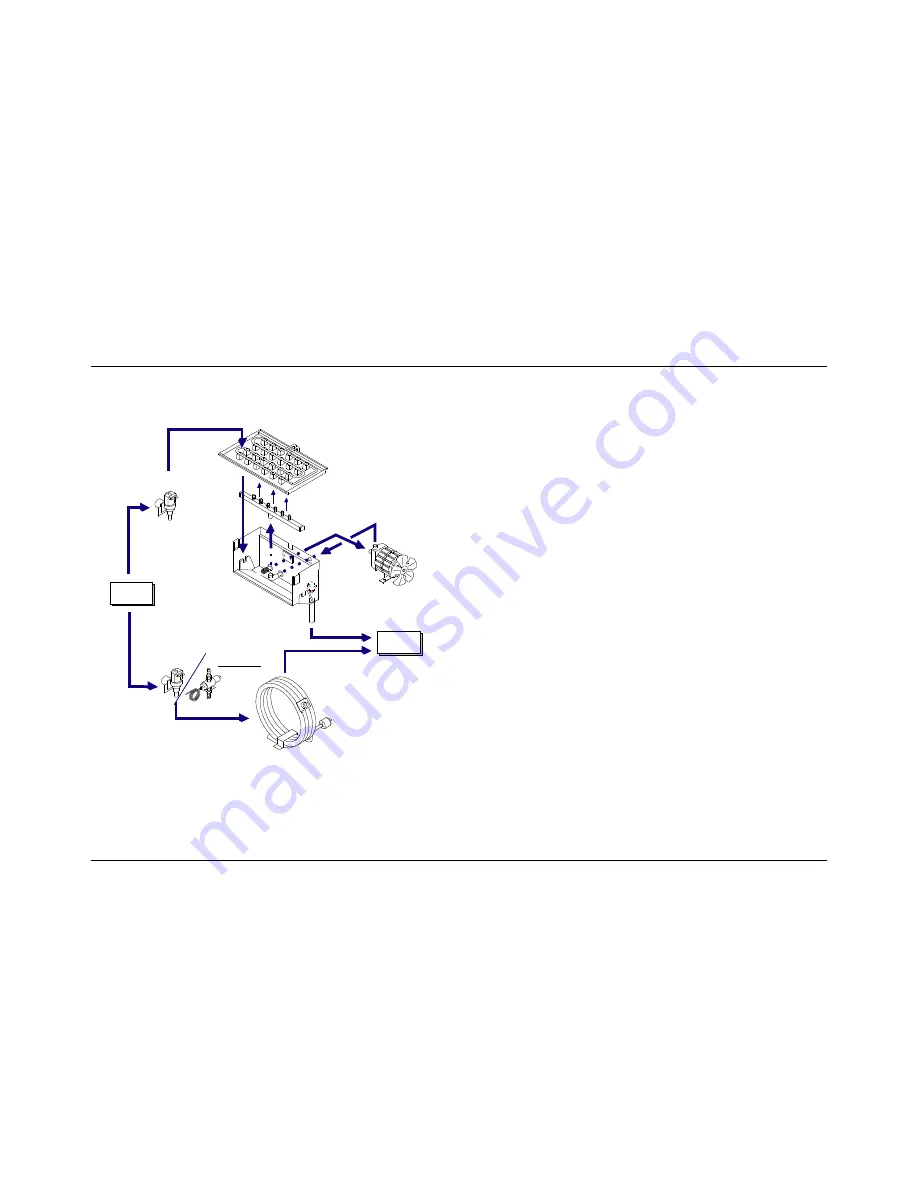
The following diagram shows the main concepts of the hydraulic 
circuit: 

Evaporator

Water-inlet

valve

Water

Supply

Water-inlet

valve

Water

Drain

Water

Condenser

Spray-bar

Pump

Overflow tube

Water Basin

CB1565 ONLY

Pressostatic

Valve


The  water  supply  circuit  of  the  basin,  the  water-inlet  valve,  the 
pump  and  the  evaporator  are  on  all  machines  of  the  ‘CB’-line; 
the water condenser circuit, on the contrary, is on water-cooled 
versions only. 

Water-inlet valve 

It works during the defrosting phase and allows the water to flow 
on  the  evaporator,  having  two  goals:  1

st

.  one  is  to  warm  the 

evaporator  help,  in  this  way,  the ice cubes detaching; 2

nd

. one, 

the  water  falls  into  the  basin,  restores  the  ideal  level  to  start  a 
new production cycle. 

The  second  water-inlet  valve  allows  the  water  flow  of  the 
through the water condenser. 

Water basin 

It  gets  water  from  the  water  mains.  It  feeds  the  pump  by  a 
specific pipe provided with a filter. 

Pump 

It  draws  out  water  from  the  water  basin  and  pipes  it,  under 
pressure, to the spray-bar. 

Spray-bar 

It  gets  water  from  the  pump  and,  by  means  of  its  nozzles, 
sprays  it  towards the cubes basin of the evaporator. The water 
that does not freeze, by contacting the cups (refrigerated by the 
evaporator coil), falls in the inside bin and is drawn by the pump 
once again. 

Overflow tube 

It  is  a  floodway.  All  the  surplus  water,  entering  into  the  water 
basin, comes out from it. 

Pressostatic  valve (CB1565 only) 

It is assembled only on water cooled machines. 

It  controls  and  keeps  constant  the  condensing  pressure,  by 
changing the quantity of water that flows in the condenser.  

Summary of Contents for ICE32A

Page 1: ...Mod ICE32A Production code CB316A 11 2007 ...

Page 2: ...It is strictly forbidden to reproduce this instruction manual or any part thereof AUTOMATIC ICE CUBE MAKER INSTRUCTIONS AND WARNINGS 24478 ed 11 2007 ...

Page 3: ......

Page 4: ......

Page 5: ......

Page 6: ......

Page 7: ...UP 6 2 a STARTING UP MODELS WITH CONTINUOUS DELIVERY 7 MAIN CAUSES OF OPERATING FAILURE 8 OPERATION 8 1 MODEL WITH CONTINUOUS DELIVERY 8 1 a ADJUSTING DISPENSED QUANTITY 8 2 MODEL WITH COLD WATER DISPENSER 9 MAINTENANCE 9 1 CLEANING THE FILTER OF WATER SUPPLY SOLENOID VALVE 9 2 AIR COOLED MODELS 9 3 CLEANING AND SANITIZING OPERATIONS 10 PERIODS AT A STANDSTILL The figures in this manual are of a g...

Page 8: ...t make any attempt to repair the appliance yourself Contact only professionally qualified and authorized personnel in addition to rendering any form of warranty null and void modifying or attempting to modify this appliance is extremely dangerous open and close the door carefully without slamming it do not use the ice cube container to cool or preserve food or drinks as these operations could caus...

Page 9: ...or from flowing back into the coolant circuit always make sure that the appliance is kept upright during transport storage and handling Follow the instructions given on the packaging 4 UNPACKING The appliance must be installed by authorized personnel in compliance with the current laws in force and the Manufacturer s instructions Once you have removed the packaging according to the instructions on...

Page 10: ...hat hold the front panel in place and after opening the door pull out the panel from above Fig 6 Before fitting the appliance in place the power cable must be fixed to the base plate as shown in the diagram in Fig 6 pass the plug and cable 11 through the hole 12 in the plate position the cable clamp 13 in its housing Fit the front panel back in place after making these connections 5 3 CONNECTION T...

Page 11: ...y to the power supply prepare an omnipolar circuit breaker 7 in Fig 4 with a contact opening gap of not less than 3 mm in accordance with national safety standards currently in force This switch must be equipped with fuses with the associated residual current device positioned in such a way as to be readily accessible This operation must be carried out by a specialized technician make sure that yo...

Page 12: ...that the appliance is not touching furniture or sheet metal which can give rise to noise or vibrations should any trace of water appear check the drain hole of the container to ensure that it is not clogged that the water fill and drain pipes are correctly connected and are not throttled or damaged make sure that the temperature of the air or water does not exceed the installation limit values see...

Page 13: ...e water inlet solenoid valve proceeding as follows switch off the electric power supply by means of the switch 7 in Fig 4 fitted during installation and disconnect the plug of the appliance from its socket if any shut off the water supply by turning the tap 8 in Fig 4 fitted during installation unscrew the threaded ring nut 14 of the water feed hose located at the outlet of the solenoid valve at t...

Page 14: ... the chemical and physical features of the water and after every period in which the appliance has remained at a standstill for any length of time You are advised to ask your dealer to draw up a scheduled maintenance contract that will cover the following cleaning the condenser cleaning the filter located on the water supply solenoid valve cleaning the ice tray checking the charge of coolant gas c...

Page 15: ......

Page 16: ......

Page 17: ......

Page 18: ......

Page 19: ......

Page 20: ......

Page 21: ......

Page 22: ......

Page 23: ......

Page 24: ......

Page 25: ......

Page 26: ......

Page 27: ......

Page 28: ......

Page 29: ...he hot gas valve Clean the hot gas valve or replace it Water blow by through the evaporator water inlet valve Replace the valve The compressor doesn t compress Replace the compressor For air cooled models The fan is out of order Check the fan motor If necessary replace it Check the correct working of the pressure switch Anomaly THE ICE MAKER REMAINS WITHOUT WATER IN THE BASIN Cause Remedy No water...

Page 30: ...p pipes Clean the pipes from the limestone Spray nozzles clogged Clean the spray nozzles Anomaly THE ICE MAKER DOESN T STOP WHEN THE BIN IS FULL Cause Remedy Bin thermostat Replace the thermostat or adjust it or check the probe position Anomaly THE ICE MAKER STOPS BY INTERVENTION OF THE WATER CONDENSER SAFETY THERMOSTAT PRESSURE SWITCH Water Leakage in the Condenser Cause Remedy No water supply to...

Page 31: ...it make vacuum and charge Evaporator encrusted by limestone Remove the limestone from the whole evaporator but without roughening its surfaces The water inlet valve of the water condenser doesn t close Replace the anti interference condenser placed parallel to the pressure switch Replace the valve Anomaly SHEET OF ICE UNDER THE EVAPORATOR Cause Remedy Faulty or not adjusted evaporator thermostat R...

Page 32: ...lean or direct the water jet toward the middle of the ice cubes Anomaly COMPRESSOR PROTECTION INTERVENTION Intermittent Working Cause Remedy Faulty power supply Check continuity the current carrying in Amp voltage of the electrical circuit Difficult condensation Check cleaning of the condenser and of the filter the fan working aeration in and out of the ice maker Starting capacitor out of order Re...

Page 33: ...Anomaly THE PUMP LEAKS WATER Cause Remedy Slack pipe clips Check and clamp the clips Worn ceramic seal Replace the pump External gasket broken Replace the pump Anomaly THE PUMP DOESN T RUN Cause Remedy Lack of power supply Check the contacts of the timer micro switch Lack of power Replace the run capacitor Mechanical locking Replace the pump Interrupted winding Replace the pump ...

Page 34: ... component Other electrical components short circuit and or low dielectric strength Replace the component Anomaly ICE PRODUCTION DECREASE Cause Remedy Condenser or air filter clogged Clean the filter and the condenser Bin flooded Check the water outlet pipes Ice maker without refrigerant Find the leak repair it make vacuum and charge Refrigerant blow by through the hot gas valve Clean the valve or...

Page 35: ...on and compresses them increasing their temperature and pressure A condenser made up of a series of tubes refrigerated by cold water or ventilated air carries away the heat comprised in the gas from the compressor and helps in this way the gas liquefaction The refrigerating fluid now in liquid state circulates then in an evaporator that permits an optimal heat exchange with the out room by taking ...

Page 36: ... the cubes basin and cools each small copper cup Water is sprayed on the evaporator cubes basin through the spray bar nozzles An ice layer due to the refrigerating fluid begins to form in the cups till these are completely full after some minutes Ice Falling Phase Defrosting Once the ice production time is finished the spray bar stops spraying water on the cubes basin and the hot gas valve assembl...

Page 37: ...out room and is refrigerated by air coming from a fan run by an electric motor Both of them carry away the heat comprised in the gas that comes out from the compressor helping in this way the gas liquefaction Refrigerating Filter Capillar Tube The refrigerant filter stops possible impurities and the circuit humidity The gas in liquid status goes to the evaporator through this filter and the capill...

Page 38: ...the compressor is piped to the condenser in order to get cool Hot gas valve Closed Suction line Capillar Tube Condenser Water Condenser Air Refrigerating filter Compressor Evaporator Cubes basin Defrosting The hot gas valve is open the compressed gas from the compressor is piped to the evaporator bypassing the condenser Hot gas valve Open Suction line Capillar Tube Condenser Water Condenser Air Re...

Page 39: ...er falls into the basin restores the ideal level to start a new production cycle The second water inlet valve allows the water flow of the through the water condenser Water basin It gets water from the water mains It feeds the pump by a specific pipe provided with a filter Pump It draws out water from the water basin and pipes it under pressure to the spray bar Spray bar It gets water from the pum...

Page 40: ... connected upstream the bin thermostat during the ice production phase so that the ice maker will stop only when the ice production phase is over The following scheme shows this working system Timer Utilizer Unit Bin thermostat Only in the ice production phase NB some components of the electrical circuit called Utilizer Units are always energized and do not depend on the timer status See the follo...

Page 41: ...drop in temperature of the evaporator starts the timer in order to complete the ice production phase Defrosting The timer once reached the set up time simultaneously commutes three contacts letting the defrosting phase begin Evaporator thermostat Timer Hot gas valve Water inlet valve Evaporator The pump is stopped and also the spray noozles stop on the contrary the hot gas valve is started in orde...

Page 42: ...hase allowing the water to flow on the evaporator and then into the water basin to restore the ideal water level to start a new cycle of ice cubes production Water inlet valve condenser This second water inlet valve allows the water to flow through the water condenser Contactor Energized the compressor Safety systems Safety thermostat Placed on the condenser of the water models It stops the machin...

Page 43: ...iio o on n n Hydraulic Circuit Refrigerating Circuit Electric Circuit LINE CAMME 4 CAMME 3 CAMME 2 CAMME 1 EVAPORATOR THERMOSTAT BIN THERMOSTAT TIMER MOTOR CONDENSER CAPILLAR TUBE COMPRESSOR HOT GAS VALVE SUCTION LINE NEUTRAL WATER INLET VALVE WATER SUPPLY PUMP EVAPORATOR SPRAY BAR OVERFLOW TUBE GREEN LIGHT SWITCH on off GREEN LIGHT SWITCH on off ...

Page 44: ...rating Circuit Electric Circuit LINE SAFETY THERMOSTAT EVAPORATOR THERMOSTAT BIN THERMOSTAT CAMME 4 CAMME 3 CAMME 2 CONDENSER PRESSURE SWITCH CONDENSER WATER DRAIN WATER INLET VALVE WATER SUPPLY SUCTION LINE NEUTRAL COMPRESSOR CAMME 1 TIMER MOTOR CAPILLAR TUBE WATER SUPPLY WATER INLET VALVE PUMP HOT GAS VALVE EVAPORATOR SPRAY BAR OVERFLOW TUBE GREEN LIGHT SWITCH ON OFF GREEN LIGHT SWITCH ON OFF ...

Page 45: ... Hydraulic Circuit Refrigerating Circuit Elctric Circuit LINE CAMME 4 CAMME 3 CAMME 2 CAPILLAR TUBE CONDENSER CONDENSER PRESSURE SWITCH COMPRESSOR HOT GAS VALVE SUCTION LINE NEUTRAL FAN CAMME 1 TIMER MOTOR EVAPORATOR THERMOSTAT BIN THERMOSTAT WATER INLET VALVE WATER SUPPLY PUMP EVAPORATOR SPRAY BAR OVERFLOW TUBE GREEN LIGHT SWITCH ON OFF GREEN LIGHT SWITCH ON OFF ...

Page 46: ...igerating Circuit Electric Circuit LINE SAFETY THERMOSTAT CONDENSER PRESSURE SWITCH CONDENSER CAMME 4 CAMME 3 CAMME 2 CAMME 1 TIMER MOTOR WATER DRAIN WATER INLET VALVE WATER SUPPLY NEUTRAL SUCTION LINE COMPRESSOR EVAPORATOR THERMOSTAT BIN THERMOSTAT CAPILLAR TUBE WATER SUPPLY WATER INLET VALVE PUMP HOT GAS VALVE EVAPORATOR SPRAY BAR OVERFLOW TUBE GREEN LIGHT SWITCH ON OFF GREEN LIGHT SWITCH ON OFF...

Page 47: ...lectric Circuit LINE CAMME 4 CAMME 3 CAMME 2 CAPILLARY TUBE CONDENSER PRESSURE SWITCH CONDENSER COMPRESSOR HOT GAS VALVE SUCTION LINE NEUTRAL FAN CAMME 1 TIMER MOTOR EVAPORATOR THERMOSTAT BIN THERMOSTAT WATER INLET VALVE WATER SUPPLY PUMP EVAPORATOR SPRAYERS BAR OVERFLOW PIPE GREEN LIGHT SWITCH ON OFF CONTACTOR CONTACTOR COIL CONTACTOR HP SAFETY PRESSURE SWITCH GREEN LIGHT SWITCH ON OFF ...

Page 48: ...R CAMME 4 CAMME 3 CAMME 2 CAMME 1 TIMER MOTOR WATER OUTLET PRESSOSTATIC VALVE WATER INLET NEUTRAL SUCTION LINE COMPRESSOR EVAPORATOR THERMOSTAT BIN THERMOSTAT CAPILLARY TUBE WATER INLET WATER INLET VALVE PUMP HOT GAS VALVE EVAPORATOR SPRAYER BAR OVERFLOW PIPE CONTACTOR CONTACTOR COIL CONTACTOR Hydraulic Circuit Refrigerant Circuit Electric Circuit GREEN LIGHT SWITCH ON OFF GREEN LIGHT SWITCH ON OF...

Reviews: