


11
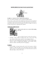
BENDING
5.
Place the rebar between the bending rollers (small moving roller and larger fixed
bending roller) where you want to make your bend, make sure you always adjust
the stopper bolt to keep the rebar at a right angle (90 degrees) to bending rollers.
6.
When positioning the rebar between the rollers, make sure that the rebar lies flat
on the unit’s surface. If the rebar is not flat on the surface, the action of the rollers
may cause the rebar to fly out or may cause damage to the stopper bolt.
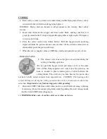
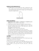
7.
Markings on the center roller indicate approximate bending angles. When the
marking is pointing towards the user the angle of the bend will be approximately
the angle indicated on the center roller.
8.
Press the safety switch lock. Pull the trigger-switch and keep depressed while the
bending arm (roller) moves and bend rebar. (If the switch
is released at an intermediate point, the bending arm
(roller) will stop.)
9.
When the bend is complete, release (OFF) the switch. If
the switch is OFF at an intermediate point, the bending
arm (roller) will stop, then open release valve lever.
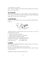
RELEASE VALVE
10.
After bend is complete, push the release valve in the direction of the arrow in
order to bring the rollers back to the start position. (Do not push trigger at the
same time as using the release valve.)
CAUTION: The cutter blade works full
stroke during the bending operation. Do not open the cutter cover. Do not try to
bend and cut rebar at the same time.
Keep hands away from moving parts while
operating.
11.
Disconnect DBC-16H from outlet when not in use and before cleaning, adjusting
or servicing. Do not disconnect plug from outlet by pulling the cord. Always
check that the switch is OFF before plugging in.
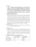
BENDER ROLLER CHART
Rebar Diameter
Fixed Center Roller
Fixed Moving Roller
No. Rebar Bend
10 mm
62 mm
33 mm
2 pieces at 1 time
12 mm
62 mm
33 mm
1 pieces at 1 time
16 mm
62 mm
33 mm
1 pieces at 1 time


