background image

DL107 Operating Manual

DL107 Operating Manual

Di-LOG

...measurably better

II. Safety Notices (continued)

6. There may still be voltage even when no 

audible/optical alarm is on.

7. The insulation type, conductor thickness, 

distance from voltage source, shielded 

conductors, other cables, socket design, 

and other factors may adversely affect test 

result. If there are any uncertainties, please 

use other methods to verify the voltage.

8. Do not assume neutral or earth wire is 

safe to touch. Incorrect or poorly connected 

circuits may cause conductors to be charged.

9. When low battery indication appears, 

please replace the batteries.

10. When using the detector, 

please keep 

fingers behind the finger guard 

before the 

clear detector head and do not cover.

11. Comply with local and national safety 

regulations and requirements.

12. The detector will not detect any voltage if:

   a. The conductor is shielded.

   b. The operator is not in contact with the 

ground or isolated from an effective grounding 

point.

   c. The voltage is DC.

13. The detector may not detect any voltage if:

   a. The operator does not hold the detector.

   b. The operator is wearing gloves.

   c. The conductor under test is partially 

buried or in earthed metal conduit.

   d. The magnetic field generated by the 

voltage source is blocked, suppressed or 

interfered with.

   e. The frequency of the voltage being 

detected is not a perfect sine wave and may 

be distorted by harmonics

   f. The detector is used outside of the 

operating specifications (see Technical 

Specifications for details)

4

Summary of Contents for DL10 Series DL107

Page 1: ...DL107 Voltage Detector 24 1000V AC Voltage Detector with High Low Sensitivity Instruction Manual ...

Page 2: ...anual Di LOG measurably better Contents I Overview 3 II Safety Notice 3 III Instrument Symbols 5 IV Specification 6 V Display and Controls 7 1 Operating Instructions 7 2 Battery Replacement 9 3 Warranty Information 10 1 ...

Page 3: ...ctor to which this declaration relates is in conformity with the relevant clauses of the following standards EN 61010 1 EN 61010 2 030 EN 61326 1 EN 61326 2 2 LVD EMC The performance of this instrument operates within its specification when used under the conditions in the above safety and EMC standards The product identified above conforms to the requirements of council directive 89 336 EEC and 7...

Page 4: ...ms For example power distribution units electrical panels and electrical appliances II Safety Notices 1 Please carefully read and fully understand the warnings and operating instructions before use If the instrument is used in a manner not specified by the manufacturer the protection provided by the instrument may be impaired 2 Please test the detector on a known live source within the rated AC vo...

Page 5: ...s behind the finger guard before the clear detector head and do not cover 11 Comply with local and national safety regulations and requirements 12 The detector will not detect any voltage if a The conductor is shielded b The operator is not in contact with the ground or isolated from an effective grounding point c The voltage is DC 13 The detector may not detect any voltage if a The operator does ...

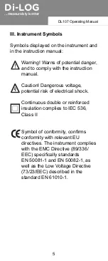
Page 6: ...or reinforced insulation complies to IEC 536 Class II Symbol of conformity confirms conformity with relevant EU directives The instrument complies with the EMC Directive 89 336 EEC specifically standards EN 50081 1 and EN 50082 1 as well as the Low Voltage Directive 73 23 EEC described in the standard EN 61010 1 III Instrument Symbols Symbols displayed on the instrument and in the instruction manu...

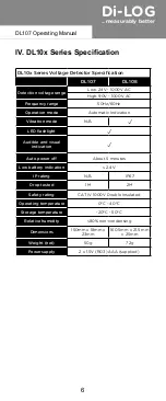
Page 7: ...mode N A LED flashlight Audible and visual indication Auto power off About 5 minutes Low battery indication 2 4V IP rating N A IP67 Drop tested 1M 2M Safety rating CAT IV 1000V Double Insulated Operating temperature 0 C 40 C Storage temperature 20 C 50 C Relative humidity 80 non condensing Dimensions 150mm x 18mm x 23mm 160 5mm x 21 5 mm x 25mm Weight net 50g 72g Power supply 2 x 1 5V RO3 AAA supp...

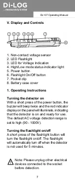
Page 8: ...e is set to high 90 1000V Turning the flashlight on off A short press of the flashlight button will turn the flashlight on off The flashlight will automatically turn off when the detector is not used for 5 minutes V Display and Controls 1 Non contact voltage sensor 2 LED Flashlight 3 LED for Voltage Indication 4 High Low mode status indicator light 5 Power button 6 Flashlight On Off button 7 Pocke...

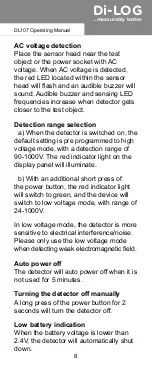
Page 9: ...of 90 1000V The red indicator light on the display panel will illuminate b With an additional short press of the power button the red indicator light will switch to green and the device will switch to low voltage mode with range of 24 1000V In low voltage mode the detector is more sensitive to electrical interference noise Please only use the low voltage mode when detecting weak electromagnetic fi...

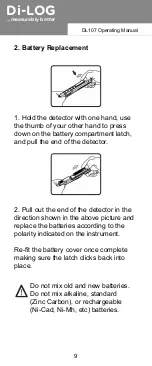
Page 10: ...pull the end of the detector 2 Pull out the end of the detector in the direction shown in the above picture and replace the batteries according to the polarity indicated on the instrument Re fit the battery cover once complete making sure the latch clicks back into place Do not mix old and new batteries Do not mix alkaline standard Zinc Carbon or rechargeable Ni Cad Ni Mh etc batteries 9 ...

Page 11: ...ty only valid with proof of purchase Faults in manufacture and material defects will be rectified by us free of charge provided the instrument has not been tampered with and returned to us unopened Damage due to dropping abuse or misuse are not covered by the warranty Di LOG Ltd Unit 28 Wheel Forge Way Trafford Park Manchester M17 1EH UK Tel 44 0 161 877 0322 Email sales dilog co uk Website www di...

Page 12: ......

Reviews: