background image

20


DHOLLANDIA 

8.4


INSTALLATION OF THE STANDARD FIXED FRAME 

8.4.1


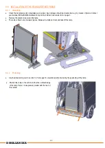
Unpacking 


Check the delivered goods immediately upon arrival. Any damages should be documented e.g. by means of photos. Contact 
your national DHOLLANDIA distributor to report the incident. See contact info on page 3. 


Remove the plastic wrap around the ramp. 


The ramp is fixed to two transport pieces. Release the bolts and nuts and take off the ramp. 


8.4.2


Positioning 


Use the dimensions given in section 7.4 from page 14 onwards as reference during the positioning of the ramp. 


Position the ramp in the vehicle so that the outboard edge 
of the ramp frame + base plate is parallel with the rear of 
the vehicle. 


Summary of Contents for DH-AI02.04.01

Page 1: ...N Belgium Tel 32 0 9 349 06 92 Fax 32 0 9 349 09 77 e mail info dhollandia be website www dhollandia com Read the manual in its entirety before operating the lift Keep this manual in the vehicle cab a...

Page 2: ...I 18 8 1 Installation kit scope of delivery 18 8 2 Preparation 18 8 3 Handling 19 8 4 Installation of the standard fixed frame 20 8 5 Installation of the optional pivoting frame OAF820 L 25 8 6 Drilli...

Page 3: ...p Contact your national DHOLLANDIA distributor See page 3 for contact info NOTICE DANGER indicates an imminently hazardous situation which if not avoided will result in death or serious injury white l...

Page 4: ...e that results from operating a ramp that has been modified from the original design without explicit written approval from the manufacturer DHOLLANDIA disclaims liability for any personal injury deat...

Page 5: ...the national DHOLLANDIA distributor for a copy of the latest set of instructions see contact info on page 3 or download the latest edition from the DHOLLANDIA website www dhollandia com Country langua...

Page 6: ...opriate Personal Protective Equipment This includes but may not be limited to ANSI rated glasses with side guards or a wrap around face shield steel toe safety shoes fire resistant overalls protective...

Page 7: ...d off the galvanisation from the areas to weld Welding can cause severe damage to the electronic components of the vehicle and ramp or lift To prevent damage ALWAYS follow the instructions and precaut...

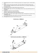
Page 8: ...igned for a fixed position of the ramp inside the vehicle no swing facility The ramp frame is equipped with quick release locks so that the ramp can be dismounted and mounted very quickly 2 Pivoting f...

Page 9: ...standard on DH AI13 optional OAP825 on DH AI12 to induce a fully automatic deployment in case of emergency 12 Platform lock mechanical lock at the side of the platform DH AI13 locking the flip over po...

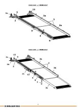
Page 10: ...9 DHOLLANDIA DH AI12 04 01 TERMINOLOGY DH AI13 04 01 TERMINOLOGY...

Page 11: ...10 DHOLLANDIA DH AI12 10 01 TERMINOLOGY Portable ramp DH AI02 04 01 TERMINOLOGY...

Page 12: ...entation If the actual dimensions go outside of the maximum installation parameters DON T continue and contact your national DHOLLANDIA distributor for further advice Verify and make sure that the veh...

Page 13: ...height Perform a risk analysis in function of the expected use the loads their weight and means of propulsion and the maximum ramp angle acceptable for the end user Make sure that the embarkation and...

Page 14: ...the vehicle contact your DHOLLANDIA distributor Practical check On technical drawings in paragraph 7 4 a bumper clearance curve is drawn Use the dimensions on this drawing to verify the suitability of...

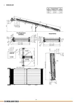
Page 15: ...14 DHOLLANDIA 7 4 TECHNICAL SPECIFICATIONS DH AI12 04 01...

Page 16: ...15 DHOLLANDIA DH AI12 10 01...

Page 17: ...16 DHOLLANDIA DH AI13 04 01...

Page 18: ...17 DHOLLANDIA DH AI02 04 01...

Page 19: ...ey are to be provided by the installer In case something is missing contact your national DHOLLANDIA distributor See contact info on page 3 Or refer to the parts list to find replacement parts 8 2 PRE...

Page 20: ...h as a forklift 1 by its forks or with slings a gantry crane hoists 2 etc to secure the platform and prevent it from falling Make sure these lifting aids are fit for purpose sufficiently strong and in...

Page 21: ...port the incident See contact info on page 3 Remove the plastic wrap around the ramp The ramp is fixed to two transport pieces Release the bolts and nuts and take off the ramp 8 4 2 Positioning Use th...

Page 22: ...on page 14 If technically possible it is recommended to mount the ramp in the center of the vehicle but it can be installed in asymmetric position as well E g in function of the bolt positions and po...

Page 23: ...n page 42 NOTICE It is essential that bolts and nuts used to mount the lift frame to the vehicle chassis are fastened with the required torque by means of a proper torque wrench See appendix 11 2 on p...

Page 24: ...d in the kit Position the ramp over the ramp fixations and engage the quick release locks at both sides The quick release lock is adjustable in length It is set at the factory but verify this during i...

Page 25: ...oints The kit includes two times the assembly that is shown below for both sides of the ramp A The base plate provides two additional fixation opportunities As these are located underneath the ramp fr...

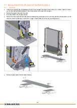
Page 26: ...DIA distributor to report the incident See contact info on page 3 Remove the plastic wrap around the ramp The ramp is fixed to two transport pieces Remove the ramp frame from its base plate by releasi...

Page 27: ...ng with the rear sill of the vehicle floor the bumper or other possible obstructions Use the provided bumper clearance dimensions in section 7 4 or place the ramp frame over the base plate to verify t...

Page 28: ...nboard from its default position across the door aperture to the longitudinal position alongside the side panel of the vehicle body wheel boxes internal racking or seating other equipment etc Out 93 I...

Page 29: ...pendix 11 2 on page 42 NOTICE It is essential that bolts and nuts used to mount the lift frame to the vehicle chassis are fastened with the required torque by means of a proper torque wrench See appen...

Page 30: ...the bolts and nuts over a wider area Mount these between the underside of the vehicle floor and the nuts of the mounting bolts If the vehicle floor is not sufficiently strong to support the ramp and...

Page 31: ...ched to the ramp fixations To adjust the length release the nut on the threaded part of the lock Turn the eye to shorten or lengthen the lock Fasten the nut firmly after final adjustment 8 5 5 Additio...

Page 32: ...tion points and prepare solutions in the event that drilling interferes with chassis beams fuel tank or other vehicle components spare wheel carrier etc Refer to the FITTING AND BODY BUILDING INSTRUCT...

Page 33: ...it from moving forward in case of heavy braking or a front collision One end of the belts is already premounted to the platform The other end must be attached to a stronger structural element of the b...

Page 34: ...ightly Loosen the bolts and move the door protection rubber to a suitable location In some cases the desired position can t be reached without taking out the handles Take out the orange caps at the en...

Page 35: ...the platform to alert surrounding traffic Apply the safety decals to the ramp and the vehicle body before delivery to the customer see section 10 on page 38 Work through the CHECKLIST FOR THE PRE DELI...

Page 36: ...I12 10 01 ramps the support feet can be slid in and out Deploy the ramp in its open work position Release and dismount the bolts that hold the 2 tubes of the support feet together Extend or retract th...

Page 37: ...port feet slightly too short Make sure that in final position the tip of the flip over point touches the ground Mount the bolts again and fasten the bolts and nuts with the required torque See appendi...

Page 38: ...ents To adjust their position loosen the 2 bolts just enough so that the handle can be moved up and down in the profile Reposition the handles as per your needs Test the new position Ensure the platfo...

Page 39: ...ble warning decals must be immediately replaced Get replacement decals from DHOLLANDIA Contact your national DHOLLANDIA distributor See page 3 for contact info The operator should comply with all affi...

Page 40: ...LS INSIDE THE VEHICLE The following decal is supplied loose with the lift and shall by affixed by the installer near the lift at a location clearly visible to the operator preferably inside the vehicl...

Page 41: ...l Protect yourself from falling off the platform or vehicle floor Crushing shearing hazard Keep feet away from moving parts Wear safety gloves Slipping hazard Wear safety toe shoes Tripping hazard Wea...

Page 42: ...linder SLIDE OUT the platform Unlock Disengage the mechanical locking system SLIDE IN the platform Lock Engage the mechanical locking system Push the stabilising LEGS DOWN Switch ON the electrical pow...

Page 43: ...ill tightened in accordance with required torque Retighten if required Use a calibrated torque wrench to tighten bolts and nuts to the prescribed torque value NOTICE WARNING Incorrect too soft or too...

Page 44: ...dequately protected against corrosion The support feet underneath the platform have been adjusted correctly see 9 3 1 on page 35 The support rod on ramps with optional pivoting frame has been adjusted...

Page 45: ...orized DHOLLANDIA service agents and using only authorized OEM DHOLLANDIA replacement parts Consult the separate MAINTENANCE AND REPAIR MANUAL for safety instructions maintenance guidelines and troubl...

Reviews: