background image

9

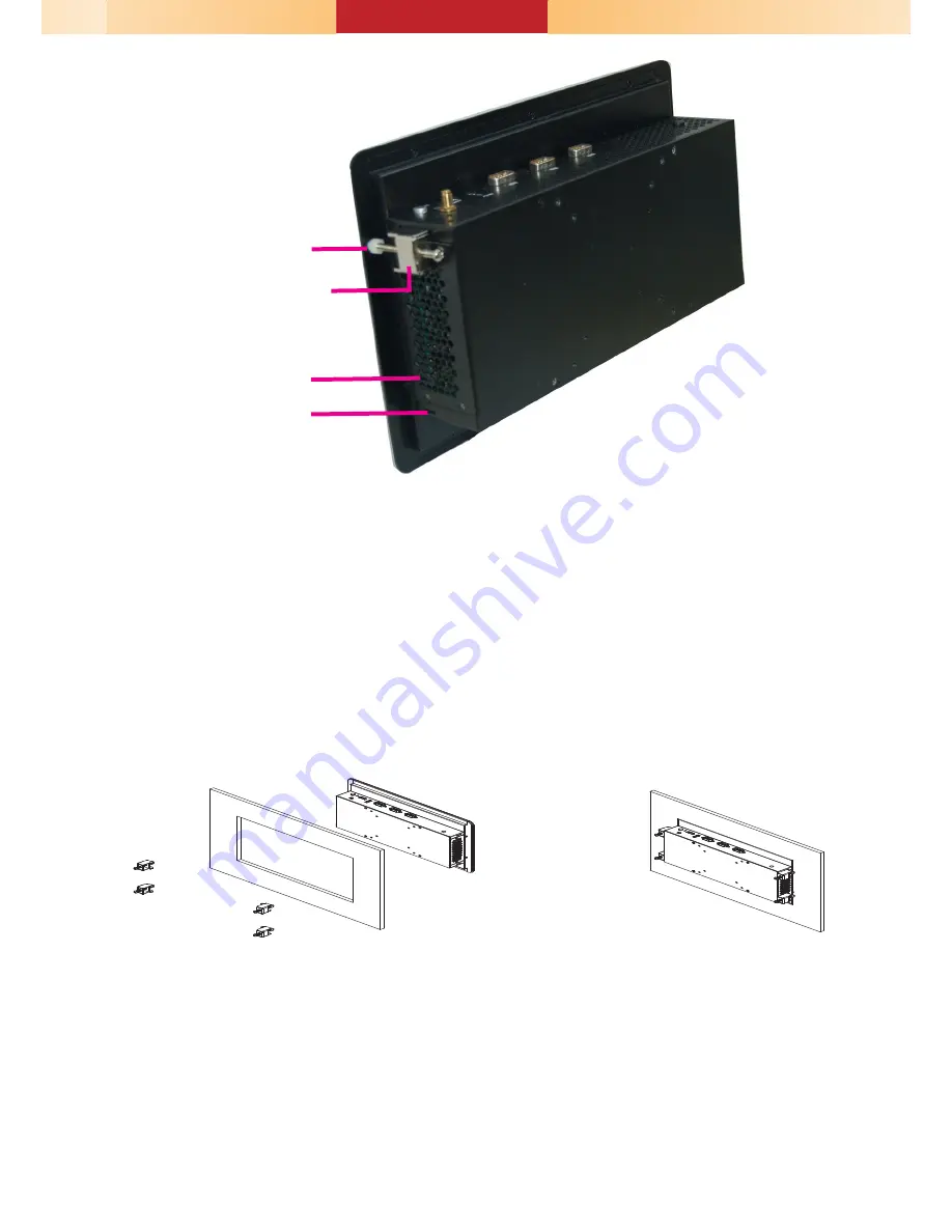
5.  The first and second clamps must be positioned and secured diagonally prior 

to mounting the rest of the clamps. Tighten the clamp’s screw using an electric 

screwdriver by pressing the white plastic cap onto the back of the panel. The 

illustration below shows that all clamps are properly mounted.  

272

169

Slit for mounting the clamp

Mounting clamp

White plastic cap

Summary of Contents for VP101-BT

Page 1: ...n screen to install drivers utilities and software applications required to enhance the performance of the system and a user s manual for your reference Insert the CD into a CD ROM drive The autorun screen will ap pear If after inserting the CD Autorun did not automatically start please go directly to the root directory of the CD and double click Setup Please install all required drivers 1 VP101 B...

Page 2: ...be a CANbus Controller Area Network interface instead VGA USB 2 0 LAN 2 Line out LAN 1 MIC in VCC ACC GND Connects to car battery COM 3 RS232 RS422 RS485 COM 5 RS232 Antenna hole COM 1 2 RS232 RS422 RS485 HDMI COM 4 8 bit DIO CANbus USB 3 0 Reset switch Status LED Power button ...

Page 3: ...ines and follow the procedure to open the system 1 Make sure the system and all other peripheral devices connected to it have been powered off 2 Disconnect all power cords and cables 3 The 12 mounting screws on the bottom and two sides of the system are used to secure the cover to the chassis Remove these screws and then put them in a safe place for later use Chassis screw Power board micro SD Min...

Page 4: ...i connection 1 Grasp the Mini PCIe card by its edges and align the notch in the connector of the card with the notch in the connector on the system board 2 Push the Mini PCIe card down and use the provided mounting screws to se cure the card on the system board Note The system also has two additional full size Mini PCIe slots that use PCIe PCIe USB 3G GPRS CANbus signals and mSATA SATA signals int...

Page 5: ...rive on the HDD bracket Place the HDD bracket back to the system and secure the drive in place with the provided mounting screws 1 SATA HDD bay is located under the power board Please remove the power board first to uninstall the HDD bracket SATA connectors on the board SATA connectors SATA Mounting screws Power board Mounting screws SATA bracket Mounting screws ...

Page 6: ...ets Bracket screws 1 Select a place on the wall where you will mount the system 2 Use the provided mounting screws to attach wall mount bracket 1 to the wall Mounting Options Wall mount Wall mount bracket 1 Wall mount bracket 2 Wall mount bracket 1 Mounting screw ...

Page 7: ...t bracket 2 to the rear of the system 4 Slide the system to wall mount bracket 1 to attach the two brackets with the hooks Then tighten the screw to secure the assembly in place Screw Wall mount bracket 2 Mounting screw Mounting screw Hooks ...

Page 8: ...itted into the panel properly 3 Insert the system from the outside surface of the panel into the mount ing hole until it is properly fitted against the panel 4 Position the mounting clamps along the rear edges of the system and insert them into the slits around the system www dfi com Panel mount The panel mounting kit includes the following 6 mounting clamps 132 20 210 50 5 Panel Mounting hole 272...

Page 9: ... mounting the rest of the clamps Tighten the clamp s screw using an electric screwdriver by pressing the white plastic cap onto the back of the panel The illustration below shows that all clamps are properly mounted 272 169 Slit for mounting the clamp Mounting clamp White plastic cap ...

Page 10: ...tal I O 4 7 Output State VGA DC in from Power board DDR3L DDR3L DDR3L DDR3L DDR3L Intel Atom E3800 Series Intel WGI210AT Nuvoton NCT6106D ASMedia ASM1442 Intel WGI210AT SMSC USB4604 SIM Card NXP PTN3460 Standby Power LED www dfi com USB Power Select 0 JP5 1 2 JP6 5 7 JP7 5V_standby default 1 2 On 5V 2 3 On Clear CMOS Data JP24 Normal default 1 2 On Clear CMOS Data 2 3 On Auto Power on Select JP25 ...

Page 11: ...On 30 sec On Off 1 min Off Off 5 min SW1 3 System off delay enable disable On Default Enable delay time setting adjust able by SW1 6 1 7 and 1 8 as shown in the table below Off Disable System off delay 0 sec SW1 6 1 7 and 1 8 System off delay time setting 6 7 8 Time On On On 30 sec default Off On On 1 min On Off On 3 min Off Off On 5 min On On Off 10 min Off On Off 15 min On Off Off 30 min Off Off...

Reviews: